So if you followed my last emulator series, you’ll know that I built up a lot of caches of shapes (characters and sprites) on demand, and then drew them when required. This works great for old consoles, and computers with character map screens, because on the whole, games tend not to change character set images very often, just the actual character map screen, which referenced these images. Because these kinds of machines have pretty good hardware support, they don’t have to resort to shifting bitmaps around, there are much easier ways of doing things.
On a ZX Spectrum however, we have a single bitmap screen, with no hardware support at all. This means as soon as a game scrolls, the whole screen changes, and you’d have to refresh the entire cache. Sure, there would be lots of games that worked just great – Manic Miner, Monty on the Run – single screen platformers for the most part, but nothing that scrolled.
Because of this it means you have to find a way of drawing the spectrum screen from scratch, every frame. A tall order. The spectrum has a resolution of 256×192, or 49,152 “dots”. While it’s a fair bet that theres more off than on, you would still have to check every pixel to see if you needed to plot anything. Another way of doing this would be to have 256 sprites, of 1×8 pixels in size, with the bits set correctly, then draw pixels 8 at a time. This means you’d be drawing 6,144 sprites – certainly doable, if it wasn’t for the attribute map of course. For each 8×8 cell, the Spectrum can change the paper and ink colours (foreground and background), and that complicates things. While we could no doubt draw that number of sprites, it’s an open question as to whether we could run the render loop fast enough – while emulating the machine at the same time.
So that as they say, was that. A bitmap screen means we can’t do it the way I have been, so there was no real point in even trying…. Then I had a brainwave…. and it’s one that I’m still considering the implications of on other emulators.
Sure, we can’t render the screen pixel by pixel, but…………..and how about this for radical…. so lets not try and cache a screen that changes all the time, but lets put the WHOLE of Spectrum RAM onto a texture, and give the GPU access to everything – and it can convert the actual, raw screen memory on the fly!
I’ll let this just sink in a little………. While you’re thinking about that though, here’s what a snapshot of ManicMiner looks like as a 256×256 texture (the 48K spectrum having a 64K address space, and where 256×256 = 65536). A spectrum screen is easy to get hold of from an .SNA file, as they are just a pure memory dump and the current register values. So if we take one of these snapshots, and put it onto a texture, this is what it looks like:

As tiny as this is, it really is the WHOLE the ZX Spectrum memory. You can see there are several bands to it, the top section with a thick while line under it, is the ROM (which isn’t part of the SNA file, but I’ve added it), after that the area with spaces and rectangles is the actual screen, and the rest is the game. The Spectrums screen starts at 16384 ($4000 in hex) and is 6144 ($1800) bytes long – it can not be moved. The attribute screen follows it.
So… now that we have a snapshot loaded into a texture (or rather a surface), all we need to do to keep is to keep it it up to date. To do this whenever the spectrum emulation does a POKE() into memory, we also execute a draw_pixel_colour(…) onto the surface image. We plot the value as a grayscale so it’s easy to visualise, but we certainly don’t have to, we only need a single value. A surface texture like this is actually 4 times the memory we need (ARGB channels, each hold 64K of data). So… if we’re going to do this, just how many times a frame will a spectrum need to update the surface? Can we even handle that?
Well, turns out not much – only a few thousand times a frame – probably even less than the cache regeneration on a bitmap game on the C64! And actually, we can refine this even more. Because as the screen is in a fixed location and a fixed size, we don’t need to plot any point outside of the screen address range , and this cuts down the pixel requirements even more. First, lets look at how we get a snapshot onto the surface…
/// LoadSNA(filename)
var SNA = buffer_load(argument0);
var add=16384;
var count=0;

// RAM image starts at 27 bytes in....
for(var i=27;i<(49152+27);i++){
    var b = buffer_peek(SNA,i,buffer_u8);
    Poke( add++, b );
    count++;
}
buffer_delete(SNA);
This loads a Spectrum .SNA file, and then copies it into memory using our Poke() command where poke is this….
You can see the address is broken up into an X,Y by using the lower 8 bits as X and the upper 8 bits as Y, and makes it very simple to access this “grid” of data. This now means as a game runs, the GPU “memory” will also be updated. Now comes the really fun part – how can the GPU use this data?
Before getting into decoding a spectrum screen, lets consider what the GPU has to work with. First, it’ll get the two triangles we’re drawing, and as part of this is the texture coordinates. These 0.0 to 1.0 UV coordinates tell us exactly where in the screen we are on U and V (or X and Y if you like). We then need to convert these 0.0 to 1.0 value into something that can use to access the screen memory. We know the screen RAM is 256×192, so we take the 0.0 to 1.0 value on U and multiply it by 256.0 giving us the X coordinate, and then take the 0.0 to 1.0 on V and multiply it by 192.0, giving us the Y coordinate. We’ll then need to floor these as they will have fractions and we want whole values so we can get the actual pixel coordinate. This might sound pretty complicated, but it’s pretty simple….
const vec2 Size = vec2(256.0,192.0);
void main()
{
   vec2 pos = floor( v_vTexcoord * Size );
}
This has now converted our UV’s out of 0.0 to 1.0 texture space, and into 0 to 255, and 0 to 191 coordinate space giving us proper X and Y coordinates – much better. Now we need to work out the spectrum memory address, that is the address on the screen the UV’s are pointing to. This now gets much more complicated… The spectrum screen address requires us to shuffle bits around, and that’s very tricky in floating point. To do so, you have to use floor(), mod() and subtraction to isolate the parts you want, and then extract them.
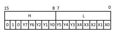
The diagram above shows how to work out a byte address on the spectrum screen, and you can see from this that while the X coordinate is simply the lower 5 bits (0 to 31), the Y coordinate is split up all over the place. The 1 at the top is the base address 16384 = %0100000000000000 in binary being added on.
So first, how do we extract the bits? Well to get the top two bits of Y, we simply shift them down by 6 bits, or rather since this is floating point maths, we divide by 64.0, then floor() the result. This moves Y7_Y6 down into the the first two bits and the floor() removes the lower bits (which have now become fractions), where we can then scale them up to the correct location later. To get Y2_Y1_Y0, we use mod(8.0), as this gives us the remainder of a divide by 8 (or a shift right 3 if it were integer). Lastly, to get Y5_Y4_Y3, we subtract off the bits we extracted for Y7_Y6, divide by 8.0 and then floor() to remove the lower Y2_Y1_Y0. Once this is all done, we have the bits in a state where we can now reorder them. All this complicated explanation looks like this in code….
float y7_y6 = floor(yy/64.0);                   // upper 2 bits
float y2_y0 = mod(yy,8.0);                      // keep lowest 3 bits
float y5_y3 = floor((yy-(y7_y6*64.0))/8.0);     // middle 3 bits
Which obviously looks much easier. Now we just have to use these to work out the index into the spectrum screen RAM, and then add on the base address, which we do like this….
float xx_byte = floor(pos.x/8.0);
float address = 16384.0 + (xx_byte + (y7_y6*2048.0) + (y2_y0*256.0) + (y5_y3*32.0));
The xx_byte gives us the byte index, rather than the pixel index, and we then simply add that on. But now, we have a value “address”, which is the current address in the spectrum RAM we’re interested in processing. Pretty sweet!
All we need to do now is write a Peek(address) function for the GPU to get the byte, and we do that by again splitting the X and Y values (as we did on the POKE() in GML), and re-scaling it all back into 0.0 to 1.0 space for a texture lookup.
const vec2 TextureSize = vec2(1.0/256.0,1.0/256.0);
float Peek(float _address)
{
    vec2 index = vec2( mod(_address,256.0), floor(_address/256.0 ) ) * TextureSize;
    return (texture2D( gm_BaseTexture, index )*255.0).r;
}
This will return us the byte of spectrum memory from the screen. If we just used this, we’d get a very blocky version of the screen – like this..

The reason it comes out blocky white rather than a grayscale (as you’d expect), is because our PEEK() routine returns a 0.0 to 255.0 number, and gl_FragColor expects 0.0 to 1.0 values, so it’s being saturated down to 1.0 all the time. If we divided the value by 255.0, then we’d get an odd grey-scale version of this screen. However, this isn’t what we’re after so we’ll move on….
Of course, once we have this the next part is to extract the bit we require (since a single byte of RAM is 8 bits). If you remember we removed the pixel index in favour of the byte index to calculate the address, but this time – we want only the bit value (0 to 7), and once we have this, we can extract the correct 0 or 1 from the byte of spectrum RAM – exciting stuff!
//
//  given a byte, and a bit number, return a 0 or 1 if its set/unset
//
float GetBit( float _value, float _bit)
{
    float scaler = pow(2.0, 7.0-_bit);
    return mod(floor(_value/scaler), 2.0);
}
This will extract the bit for us, and now we just need to call it….
float mem = GetBit( Peek(address) ,bit);
gl_FragColor = vec4(mem,mem,mem,1.0);
And this will now give us a fully black and white version of the spectrum screen – direct from it’s RAM.

How cool is that!! Now that we have this, it’s a small step to get the proper colours – the hard part, as they say….is done. The attribute screen is much simpler, as it’s just an X by Y grid of values – and no funny interleave. So this time, you just take the Y pixel position, divide if by 8, floor() it, them multiply it by 32 and add on the X byte position, and you have an index into the attribute screen. Add on the base address, and you’ve got another value to PEEK() with.
You’ll then have to split this value into two – ink and paper (which are 0 to 7 values), and while your at it – extract the flash (bit 7) and bright (bit 6) bits.
With this done, you can now lookup the colours – just like we did in the C64 emulator to get real ARGB values, and then depending on if we had a 0 to 1 pixel, use the paper or ink colours.
if( mem!=0.0){
   mem = ink_col;
}else{
   mem = paper_col;
}
gl_FragColor=GetColour(mem);
With this done…. we finally have a real looking ZX Spectrum screen!

Now, there are a couple of extra bits to deal with, bright, flash and the border. We’ve already extracted the bright bit, so you can handle that easily enough, but flash needs an external input. The GPU has no way of doing “time”, so the CPU will have to handle that, and pass in a 0 or 1 depending on the current flash state. You can either do this through constants, or you can pass in a value via a channel in the vertex colours. I opted to use the vertex colour because I also pass in the current border colour in this manner as well, so it works out pretty well.
Speaking of the border…. Because we deal with the spectrum screen in terms of 0 to 255 and 0 to 192, we can simply increase these values and do a screen size of 320×256. This gives us 32 pixels around the whole screen. We can easily detect this inside the shader once we’ve worked out the X and Y coordinate, and display the border colour when we’re in that zone – like so…
// Top and bottom border?
if( yy<32.0 || yy>=224.0 )
{
    gl_FragColor = GetColour( v_vColour.r*255.0 );
}
else
{
   // Side borders?
   if( xx<32.0 || xx>=288.0 )
   {
        gl_FragColor = GetColour( v_vColour.r*255.0 );
   }
   else
   {
        // process screen...
   }
}
So unlike the C64 where I simply couldn’t afford to draw the border, here the shader does everything, and it barely registers as a blip in the FPS. With the border added, we now have a fully functional ZX Spectrum screen, and after a frame of emulation, we can just draw it using a simple draw_surface(), surrounded by a shader.
Although… it doesn’t quite end there….. Just like the C64 emulator, Spectrum programmers were sneaky, and as the raster draws the screen, they will update it, this means by the time the frame has finished, it’s probably not the same as it would have looked if we drew it as we went. The game Cobra shows this pretty well…
The reason for the flicker, is because this programmer would draw things in such a way that it didn’t flicker, and he didn’t have to double buffer the screen, but in doing so, screen RAM at the end of the frame wasn’t the final image displayed to the user. In order to get around this, I yet again draw the screen in chunks – 16 pixel high strips this time. I could do single line strips, but unless I’m doing Hires colour simulation (where the attributes are changed every line), I just don’t need that, and games never did much of this because it consumed too much time. It should be noted that I could detect that the game has modified the attributes and then flush out a line at a time at that point, and that would allow me to “auto-swap” for Hires colour, but I’m not that fussed here.
So after every 16 scanlines emulated, I draw the next 16 lines on the screen. This works perfectly for my purposes, and makes Cobra look rock solid again.
So, there you go…. a somewhat different approach to displaying an emulated screen, but one that works incredibly well, especially for dynamically changing bitmap screens. I suspect if you did an Atari ST emulator, you could render the screen in much the same way. Anything with hardware assistance is more complicated, but as long as the GPU has access to the hardware registers, this would still work – but the shader might get incredibly large. A C64 shader dealing with sprites, characters and bitmaps – and all the funny modes they can do, would be very cool, but incredibly complex.