So my next post was going to be about tracking down my CPU bug and how the memory mapping was going to work, but then I suddenly realised I needed to do another first, on how I actually emulate the CPU – a bit more detailed at any rate. So I’ve moved all the others out by a week, and thrown this one in first….
Before you read this one, you should probably read my post on dealing with binary (An introduction to Binary) – it’ll certainly help when dealing with the emulator world as a whole. In my first post, I talked a little about how the CPU works, how it gets a stream of bytes, and how it executes a specific instruction for each one – and I was even nice enough to provide a couple of examples. Now this is all well and good, but what about more complicated ones? Instructions that aren’t just load/store or clear a flag? What do they look like, and how do we emulate everything required?
First I’m going to talk about the flags register F, and what each bit means, and how they are set/reset by the CPU. The flags register is a series of BITS, not just a true or false, so it can hold upto 8 flags at once – these are shown below.
CARRY
Just like when adding up a column of numbers yourself and getting a figure to carry over into the next column, the CPU does exactly the same. The 6502 will only add 2 bits together at once, meaning it only ever needs to carry a single 0 or 1 as shown below.
- %00 + %00 = %0 carry %0
- %01 + %00 = %1 carry %0
- %00 + %01 = %1 carry %0
- %01 + %01 = %0 carry %1
Of course… even the lowly 6502 can do more than a single bit, it can do 8 at once, but the theory is the same, as it adds each bit of the 8, it carrys over a bit if required into the next 2 bits and progresses on for all 8 bits. If there is an overflow from the final two bits, then that overflow is stored in the carry flag.
It’s also used for other things, like bit shifting. If I want to rotate 16 bits left, I’ll rotate the first 8 bits, bit 7 goes into the carry, then when I shift the next set or bits the carry bit will go into the bit 1, while bit 7 will again go into the carry.
Lastly, the carry is also used in comparisons. If I compare 50 to 100, I can see its less than it, but how does the CPU know this? Well it will subtract them, and if the carry gets set or cleared, it’ll know if its less than – or greater than, and then set the carry flag accordingly.
ZERO
This flag lets the developer know that the last operation was a zero – pretty simple really. This can range from when we load a value into a register (if it loads a 0), or if we add 2 values and it results in a 0. Also, if we compare 2 values and this is set, we know it’s the same value being compared, or even when a shift results in no bits left.
INTERRUPT DISABLE
First… what is an interrupt? Well, all being equal, the CPU reads a stream of bytes and executes them, and thats it. But with CPUS there are many other factors to take into account. What if you wanted to know when a timer fired off? You could poll it all the time, but if you are in a complex routine, you might miss it altogether – or it might be delayed too much to make it useful. So what interrupts do, is interrupt the current flow of the CPU when “something” happens. That something could be a timer going off, a raster line hitting a certain value, 2 sprites colliding, a Tape “edge” had been detected, some data has arrived on the RS232 – and so on. This means you can write your main program normally, and then have special callbacks when something interesting happens.
When these do fire off, the current PC address is stored on the stack along with the F register, then the PC is set to the contents of $FFFE/$FFFF for an IRQ (Interrupt Request) is issued. This function must then save the rest of the registers (or those it uses) and then check the various hardware interrupt registers itself, deciding what and how to act. Theres also a software interrupt, which you can throw by executing a BRK instruction. These are used for many reasons – especially by debuggers.
These interrupts are maskable. This is to say you can disable them if you choose to by setting this bit with the SEI instruction, and restoring them with a CLI instruction. While the interrupt is still flagged, it won’t be triggered until this bit is cleared.
There is another class of interrupt – the NMI, or Non-Maskible Interrupt. These are just like IRQs, but the jump through $FFFA/$FFFB, and you can’t stop them – except at the source (via the hardware register).
DECIMAL
Decimal mode is a special way of adding or subtracting and is enabled with this bit. Normally when you view a number in hex, it’ll look something like this $F8. Decimal mode caps the values to $99. So instead of when adding 1 to $79 and getting $7A, you would get $80. It’s handy for things like scores, level numbers and the like… but most devs don’t use it much.
BREAK COMMAND
This bit is set if the last interrupt thrown was a BRK instruction. The interrupt routine can check this bit to see if it was a software break, and perhaps do a single step or other custom function.
FUTURE USE
Unused….
OVERFLOW
Occurs with some arithmetic operations, but is more interesting when used with the BIT instruction, as bits 6 and 7 are transferred directly into this and the negative flag – very handy for checking flags and quickly branching on the result.
NEGATIVE
As with the carry and zero flags, this is used on comparisons, additions and subtractions. Whenever a value is loaded that is negative (128 to 255) this bit will be set. In case you don’t know, negative numbers are signified by the top bit of a value being set. So a byte can either hold 0 to 255 or 127 to -128. When a value is loaded with bit 7 is set, this flag is set, if an addition – or subtraction goes negative, this bit is set.
So… that’s the flags register. If you need to know more, you can Google the CPU and read up on it, but this is a quick overview. The reason for this intro is so I can look at a couple of more complex instruction, and talk about how you handle them.
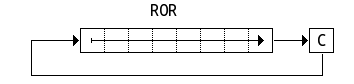
The first one I want to talk about is ROR – Rotate right through carry. This basically rotates the destination value (memory or A register) right 1 bit, with the carry going into bit 7 and bit 0 going into the carry. So if A=%10011011 and the carry flag is 0, when we rotate this we get A=%01001101 and the carry flag will now be set to %1 – as shown below….
So first depending on the opcode(there are 5 different ROR instructions), we load the value into a temporary variable, then we shift it taking into account the carry and then store it back into memory. So here’s the whole function, then I’ll go through it step by step….
// Get carry and clear flags
t = (_F&_C)<<7;
_F &= (_V+_D+_I+_B);

// Load data from source
switch (opcode) {
   case $6A : data=_A; break;
   case $66 : zpage=GETABYTE();     data=Peek(zpage); break;
   case $76 : zpage=(GETABYTE()+_X)&$ff; data=Peek(zpage); break;
   case $6E : address=GETAWORD();   data=Peek(address); Poke(address,data); break;
   case $7E : address=GETAWORD()+_X; data=Peek(address); break;
}

// Do actual ROR operation
_F |= (data&1);                 // Copy carry
data=((data>>1)&$7f)|t;         // shift bits, and clear top bit (space for old carry)
_F |= (data&128);               // copy negative bit into carry
if (data==0) { _F|=_Z; }        // is the resulting value 0? is so set the zero flag

// Store the data back in the correct location
switch (opcode) {
   case $6A : _A=data;            Cycles=2; break;
   case $66 : Poke(zpage,data);   Cycles=5; break;
   case $76 : Poke(zpage,data);   Cycles=6; break;
   case $6E : Poke(address,data); Cycles=6; break;
   case $7E : Poke(address,data); Cycles=7; break;
}
First it’s true that I could break this into 5 Separate different functions, and this would remove the switch statement, but it’s not massively important in this function as it’s not used as much as others- but it depends how fast you want things to go.
So the first part is to copy out the carry flag, then clear the flags we’re about to affect. Since the carry is the 1st bit, we can get it by shifting it up to the required place, and then masking off the rest of the bits we don’t need. This saves doing an “IF” check, as it’s always faster if you can remove IFs (within reason of course!)
The next part is the first switch statement. There are 5 opcodes that make up the following instruction.
$6A  =  ROR A
$66  =  ROR $00
$76  =  ROR $00,X
$6E  =  ROR $0000
$7E  =  ROR $0000,X
$6A is pretty easy, you just copy the A register. The next Peek()s a zero page location, while $76 takes the zero page value and adds the X register to it, then reads that. the last 2 are the same, but takes a full address instead.
The next section deals with actually rotating the data. we know that the lower bit will go into the carry, and since the carry is bit 0, then we can simply transfer it over. Next it does the actual shift right then masks off the top bit (where the old carry will come in), while copying in the old carry flag. Next, if the top bit is set, then the value is deemed to be negative, so we need to set the negative bit (bit 0) in the flags register, while if the value is 0, then we also need to set bit 1.
Lastly we need to get the data back into the source location (again depending on opcode). We don’t have to calculate too much this time, just poke the final value into the source address.
As you can see, you have to emulate every part of the CPU, including getting and setting of flags, because the CPU might shift something into the carry bit, then branch if the carry is set, or use it as part of an addition or subrtraction later on. The most complex instructions in 6502 are ADC and SBC and I was going to discuss those, but they are a tab long, and as there are 2 modes (thanks to decimal mode) they ramble on a bit.
So instead I’ll talk about subroutines and how they work. 6502 has 2 instructions for dealing with functions; JSR $4400 (jump to subroutine) and RTS(return from subroutine) and I guess technically RTI (Return from Interrupt).s
So how does this work in practice? Well, first let’s look at the code….
// Opcode20()  JSR $4400
Dush((_PC+1));
_PC=GETAWORD();
Cycles=6;
First we push the current PC (program counter) onto the stack, although the 6502 pushes address+1 (just to be annoying). But what is a stack? Well, the 6502 has 256 bytes of program stack – although to be fair, the C64 doesn’t use much of it. The stack pointer starts at $FF and works its way backwards. Here’s the Push() function…
/// Push(_reg)
pMemory[# _SP,0] = argument0&$ff;
_SP =((_SP-1)&$ff)|$100;
When you push a value onto the stack, it goes into the stack base address+SP (which on the 6502 is $100+SP), then SP is decremented by one. Pop() is the reverse…. SP is incremented, then the memory location is returned. Dush() is a double push – for 16bits rather than 8, and it simply pushes 2 bytes on the stack in the order of hight, then low.
/// Pull()
_SP =((_SP+1)&$ff)|$100;
return pMemory[# _SP,0];
Back to JSR…Once the current address+1 is pushed, we then read the call address and transfer it into the PC so that the next stream of bytes will come from this location. This instruction takes 6 cycles while RTS also takes 6 – making a call pretty expensive in 6502 land, which is why you see so many loops unrolled in the old days. Speaking of RTS, what does it do… well, as you’d expect – pops the return address, and stores it back into the PC register like this;
/// Opcode60()
_PC=(Dull()+1)&$ffff;
Cycles=6;
As you can see, the address is pulled (and 1 is added) then transferred into the Program Counter.
So there you go, this is the kind of things you have to do to get emulation to work. Do this 60 odd times, and you have yourself a 6502 core ready to rock and roll. Next time I will talk about how I tracked down my CPU bug, and how I emulate the complicated memory mapping the 6502 has at a speed that makes it a relatively free process.