These articles were first published at the start of 2015, and GameMaker has changed a lot since then – not least with the release of GameMaker Studio 2. Fortunately nothing much has changed in terms of the core tech on how this works, so it’s still a good primer for writing an emulator.
So I started this very much in the “can you even do this” spirit, and have been surprised how much I’ve been able to do with it. Sure, it does require YYC (GameMaker: Studio Compiler), but as YYC is now available to everyone, then I no longer see that as a dependency, but just another tool in the GameMaker box. There are several complications in even trying this, but the CPU emulation is “just” a program so should work easily enough, while rendering emulated memory is a tough nut to crack – but we’ll come to that in a later part. The reason for writing these posts, is that I’ve come up with some interesting tricks to over come some GameMaker limitations – as well as good tricks to just help speed up your code (much as you would in any language). So I thought it would be a good idea to share them.
Still, enough of all that, what exactly IS an emulator, and how does all this work?
Okay… so the goal behind any emulator is to be able to play the BINARY files from the original machine, directly. These file are always assembly level instructions so if you’re unfamiliar with assembler, let me give you a VERY quick overview of 8 bit assembly. Memory on 8 bit machines can store BYTES, values from 0 to 255. A 64K machine like the Commodore64 (or C64 from now on) can store 65536 of these. The CPU has what’s called a program counter (PC), and this is the current address it’s executing. The PC can be any value within the 65536 bytes available. The CPU will then stream in values from memory using the PC as it’s “current” pointer, and moving the PC one each time it reads something… much like reading data from a file.
So, let’s say the PC gets a stream, of bytes like this… $18,$A9,$50,$69,$80,$8D,$00,$10,$60. What does this mean? Well, if you look below, this is what the CPU gets from it….
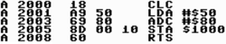
It’s a simple addition function, that add$ $50 to $80 and stores the answer in a variable (or memory location – which is all variables are). The first byte $18 is the CLC instruction – or clear carry, and just like normal maths when you have to carry a 1, this is the computer version of that that we’re clearing. Next we load the A register with $50. Registers are just very fast variables, the are memory locations inside the CPU itself, where the CPU doesn’t have to go to a RAM chip to read/write things. The 6502 has several 8 bit registers, with the exception of the PC which is 16bits. A, X, Y, PC, SP and F. A is the only general purpose register, while X and Y are index registers – registers you use in for loops if you like. PC is the program counter, while SP is the current stack pointer. F is a set of “bits” used as flags. Each of the 8 bits in this register means something – the carry flag for example is bit 0, while the negative flag is bit 7. If you want to see more on bits and flags have a read of my Introduction to binary article.
So..now that the carry is clear, and A holds $50, the next instruction ($69) is ADC – or add with carry. This will add $80 to the A register and store it back in the A register. If it overflows past 255, then the carry will be set. If the carry was already set, then 1 will be added to the result, so you end up with A=A+$80+Carry. The CPU then reads $8D which is the STA – or store accumulator instruction, and it’ll then store A into memory location $1000. Now, this may seem odd… but in a proper assembler, I’d have assigned a name to this location – like “Answer”, and I would write STA Answer. Memory locations are just places to store values, just like variables are in high level programming languages. Lastly, we get $60, which is RTS – or return from subroutine. This exits the function and returns back to where it came from (using the calling address stored on the stack using the SP register).
So there you go… a crash course in 8 bit assembler. There are lots of instructions in assembler, you can see more here.
So how do we emulate this? Well… first things first, we need an array of 65536 locations to act as our “memory”, then we need to fill it with a program we can run. Old machines have built in programs called ROMS, and these are there when the machine boots up. So the first task is to load the ROM into our memory array (pMem from now on). Once we’ve done that, we create 6 variables to act as our registers _A,_X,_Y,_PC,_SP,_F and we set them to the values 6502 would on power up. The PC is the interesting one, as its set to the value stored in $FFFC or memory – or the “reset vector”. The 6502 has several hardware vectors, Reset, IRQ (Interrupt request) and NMI (non-maskable Interrupt). So, we read 2 bytes from memory -the first byte is the low 8 bits of our 16bit register, and the second the upper 8 bits of it. This gives us the ROM “start address”.
With this done… we can now start streaming bytes, and trying to emulate the CPU.
First we read an opcode (the 1st byte of an instruction is called an opcode), and then how do we decide what instruction this is? Well, we use a HUGE switch statement! There’s a possible 256 instructions on 6502 (although not all slots are used), so we can simply do this…
opcode = GetAByte();
switch(opcode){
    case  $00:   ExecuteBRK(); break;
    case  $01:   ExecuteORA(); break;
    case  $02:   ExecuteHLT(); break;
    case  $03:   ExecuteASO(); break;
//
// Reset of the instructions....
//
    case  $fe:   ExecuteINC(); break;
    case  $ff:   ExecuteINS(); break;
}
Now, this works fine, but it will be a little slow…. Each “case” statement is basically an IF, so the larger the value opcode is, the more IFs it has to execute. So lets make a “jump table” instead. So first when we startup, we call this script…
Opcode_JumpTable=0;           // Clear the array (free memory)
Opcode_JumpTable[255]=0;      // SIZE the array

// Setup jump table script calls...
Opcode_JumpTable[$00]=Opcode00;
Opcode_JumpTable[$01]=ProcessORA;
Opcode_JumpTable[$02]=ProcessHLT;
Opcode_JumpTable[$03]=ProcessASO;
//
// rest of instruction....
//
Opcode_JumpTable[$fd]=ProcessSBC;
Opcode_JumpTable[$fe]=ProcessINC;
Opcode_JumpTable[$ff]=ProcessINS;
And now to use it, we simply do this….
opcode = GETABYTE();
script_execute( Opcode_JumpTable[opcode] );
The advantages of this, is that it’s a constant speed – no matter HOW big our table is! we could have thousands of entries in here, and it would still be the same speed.
Or it would have been…. however after writing this, @8BitWarrior said he’d being doing some tests, and it looked like YYC was better with the switch! This was very odd, but after porting the code back to a switch statement, it showed he was correct. Stranger and stranger…. So I took a look at the script_execute() code, and yes… it’s pretty nasty in there, but that wouldn’t explain it all. So I then took a look at the C++ code YYC generated, and there you go…. it keeps it as a switch statement.
Now, modern C++ compilers will usually convert switch() statements into jump tables anyway, so what appears to be happening is that CLANG is doing a better job of calling my sub functions that YYC/GameMaker is. This shouldn’t be a huge shock, as that’s what it’s supposed to be, but it also means I can now avoid the internally nasty script_execute() function.
Also…. as a side effect…. it means I can actually inline some of the smaller (or more commonly used) functions, directly into the switch statement, there by removing the call completely. So all in all…. good catch by @8BitWarrior, and proof – if you ever needed it, that you can’t know everything, and that it’s great to be proven wrong!
Now all we have to do is write all the (many) instructions! Lets take a look at a couple of them… see what they might be like.
//LDA #$44
_A=GETABYTE();
Cycles=2;
COMP(_A);
If you remember from example at the top (LDA #$50) this loads $50 into A. Well, here is our GML code that does the same…. Now aside from loading A, we also have Cycles and a COMP() function. Each instruction takes a certain amount of time, and this time dictates how many instructions we can do per frame, and per scanline (a scanline being a single pixel line of a display – the C64 had 312 scanlines, of which 200 were normally visible). We then add these cycles together after each function and it tells us where in the display we currently are.
6502 flags are set/cleared on many operations. When you load a value into a register, the flags are set to tell you if it was zero, or negative. COMP() is a fast function to help do that – via a lookup table. These could be inlined if required (but thats a lot of cut’n’pasting!)
Lets take a look at a slightly more complicated LDA example..
// LDA $4400,Y
var address=GETAWORD();
var a=address&$ff00;
address+=_Y;
_A=Peek(address);
if( (address&$ff00) !=a ) Cycles=5; else Cycles=4;
COMP(_A);
This one loads from $4400+Y, and is very handy in loops where you are setting, clearing or copying from blocks of memory. You can see there is a slight complication in the cycles, it can be either 4 or 5. This is because if Address+Y crosses a 256 byte boundary, there is another cycle involved, and we need to deal with this as well. Aside from that, it reads the 16bit address using GETWORD(), then adds on Y, and then uses that value to Peek() memory and load A.
Commands like ADC can be very complex, as the involve using and setting flags, and also something called BCD mode (binary coded decimal) which means it can store decimal numbers in a byte, and will do basic maths using it. Other instructions like CLC are very simple.
// CLC
_F&=(~_C);
Cycles=2;
So, once we’ve written ALL these instructions, and have a reasonable CPU emulation going, will the ROM just run? Well…yes and no. The 6502 also has interrupts, and the kernal ROM uses these for input. It’ll still run, but you wouldn’t be able to type anything. Still, that’s fine for now, so what else would go wrong? Well, we also have hardware registers to deal with.
Just like “built-in” variables in GML, the C64 has some built in values via it’s IO chips. The VIC, SID and CIA chips all do different things, the VIC does graphics, SID does sound, and CIA does – well, everything else. (I’ll let you google them for more info). The VIC tells us what raster line we’re on, the colours of the screen, the location of the screen in memory, and deals with hardware sprites.
The VIC sits at location $D000 in memory, and works as a kind of “overlay” to real memory – meaning you can page it out of you want. (we’ll get to RAM/ROM/IO paging later!). But for now, let’s say that as emulation progresses, you need to update these memory locations with whats happening, so than the 6502 (and Kernal) and read/set/wait on specific things. It’ll also setup colours by “poking” these into the VIC memory location, which we’ll then read to display out screen.
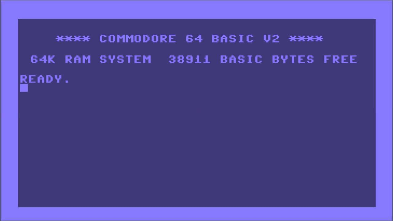
Speaking of screens…. the C64 sets up its screen at memory location $0400 (although most games move it), but for now if we run the emulator, and display what’s at this location… we “should” get to see a C64 booting up! (like this….)
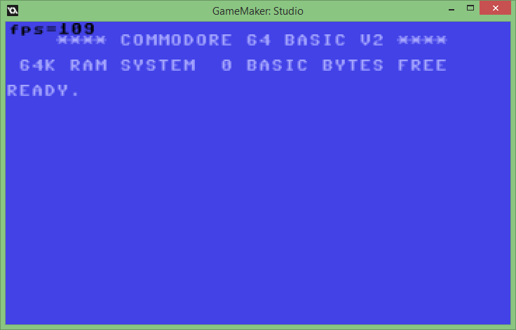
Now… how did I display this? Well, I cheated. I downloaded a C64 windows font, then I looped through the c64 memory and built up lines of strings, and just printed it using draw_text(). But still, it shows what you can get away with. I’ll improve on this later, but for now… all is going well!
or is it….that 0 BASIC BYTES FREE looks pretty wrong. Turns out, I had a couple of CPU bugs, code that worked differently in C/C++ than GML. Finding these was a task in itself, and I’ll talk about that in my next post.