To have a little break from doing #CSpect and Steam/Switch stuff, I decided to write a few basic game engines for the NEXT, and the first step in that is making a framework that can be the basis of everything. In this little tutorial I’m not aiming to teach Z80, but tech the machine itself, what the hardware can do, and how to make a game with it.
But first things first, what does a simple framework look like? Well normally when I do one I’ll setup the screen, some basic interrupt handling, input, and a file system of some kind, so lets do that. I’ll be using my SNasm assembler – though be warned it’s an unreleased one as I’ve changed the way segments are handled, and that’ll mess things up a bit. I’ll try to release a new one soon, but I’ve to fix up some other things first – though it should be easy enough to port to other assemblers if you wish to.
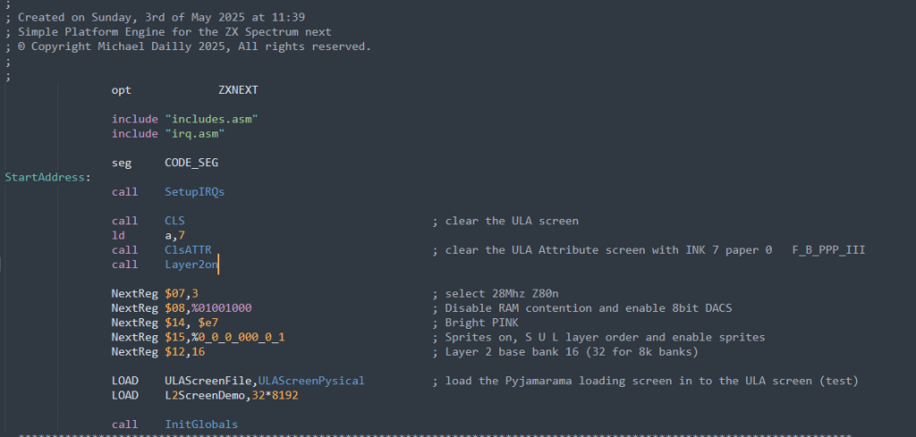
Here’s the main start up sequence, so lets go through it. “opt ZXNEXT” puts my assembler into ZX Spectrum Next mode, complete with all the enhanced instructions (NextReg, Mirror etc).
Next we include the master includes file – all our constants, macros and segment definitions, we’ll get to that in a moment. After this we include the IRQ function. This is a bog standard ZX Spectrum 48k one, we’ll enhance it to use vectors at another time, a simple framework doesn’t need that, that’s more game specific.
Next we set the code segment. So what are segments in SNasm land? These are like ORG’s that automatically track the last assembly point. For example, say I ORG $8000, assemble 64 bytes, then do an ORG $C000 and do some work there, I can then ORG $8040 to resume where I left off. “SEG” takes care of this for you, and is perfect for a larger memory model like the NEXT where you can split up memory into more manageable areas – code, data, screens, files, raw graphics etc…
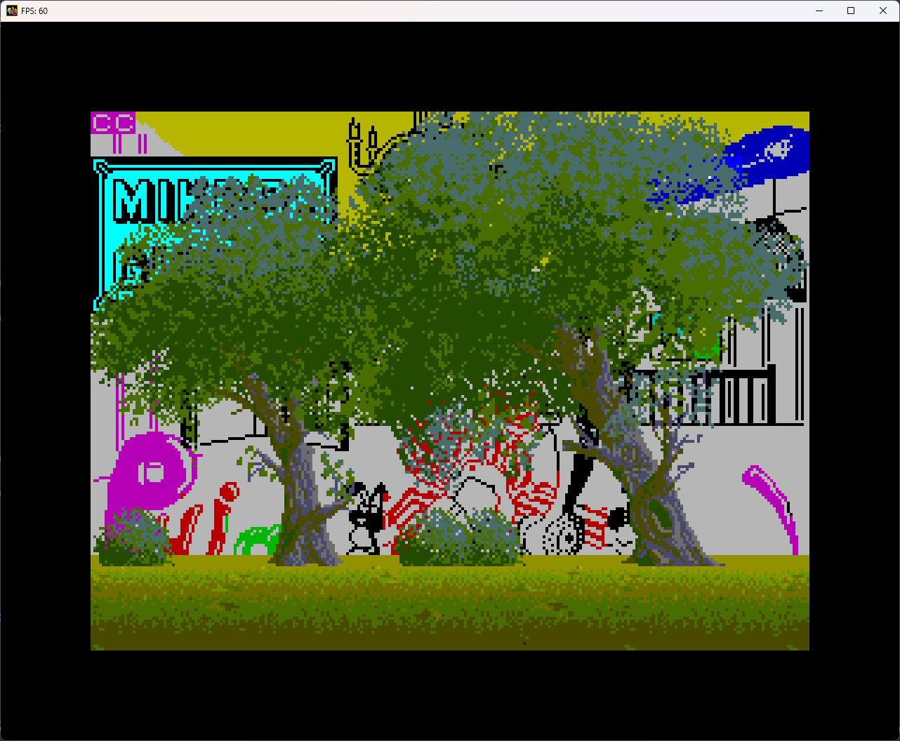
Next we clear the ULA screen and set the attributes to black paper and white ink, and after that we turn on the Layer 2 screen. Okay, before going into the next section, lets go more in-depth to the previous calls – first the IRQs.
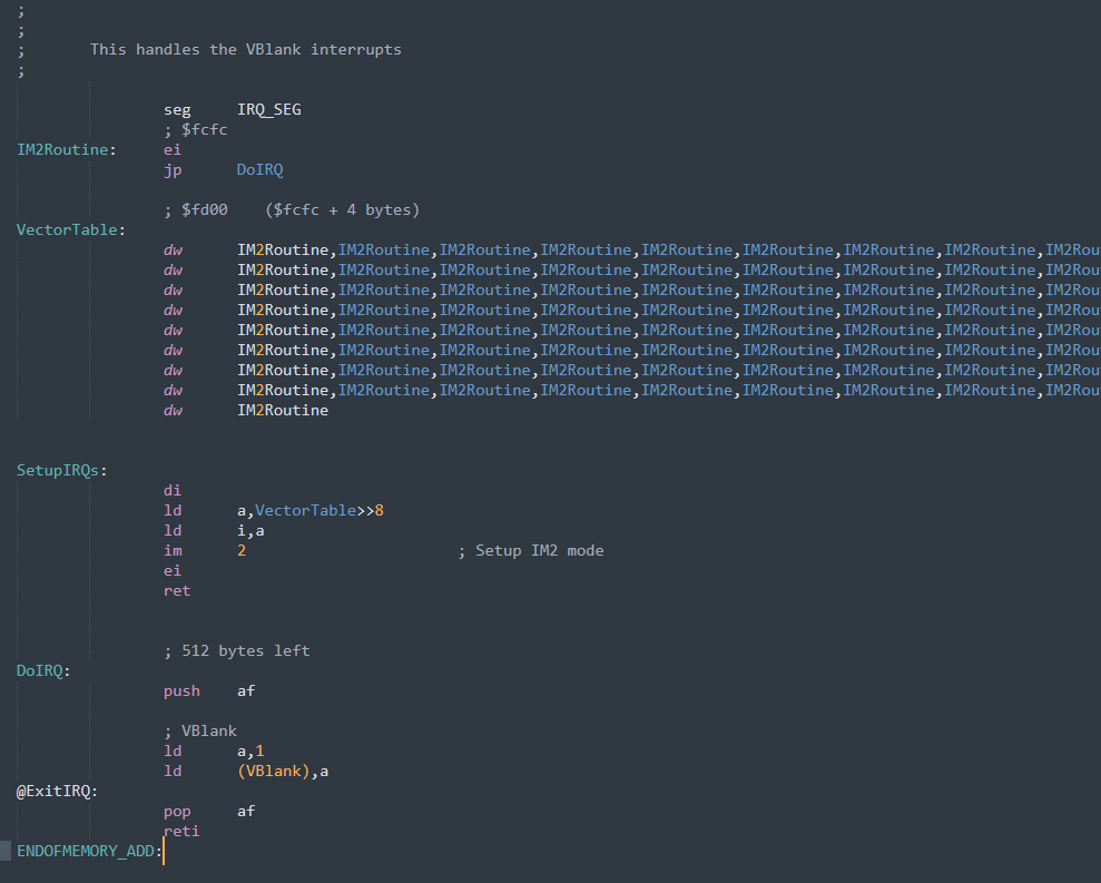
As I said before, this is a bog standard 48k ZX Spectrum VBlank (vertical blank) interrupt. This gets called every frame when the raster finished drawing the screen, and jumps back to the start – the vertical blanking period. If you look at the “SetupIRQs” function, you’ll see we disable the interrupts first (di) then setup the vector table. Now on the 48k spectrum the upper byte of the IRQ jump address comes from I register, while the lower byte varies due to the floating BUS nature of the spectrum (I think it is). To compensate for this, we make the IRQ vector the same upper and lower byte value, in our case $FCFC, so that way no matter where it reads the vector, it’ll jump to the right point.
So after setting the I register, we enable Z80‘s IM 2 mode and re-enable the IRQs. You’ll notice the $FCFC vector simply re-enables the IRQs and jumps to another address. This is simply to conserve memory as that’s 4 bytes then we hit the vector table itself. The IRQ routine itself currently just sets the VBlank flag so the main loop knows a frame has passed and we can sync up to the raster. Now, we could do more here – like flipping the screen, moving a sprite around – whatever, but for now, this is fine and that’s all the IRQs do for the moment. I place the IRQs at the very top of memory, and that means that bank can never be paged out, but that means we always have a bank that can have drawing code or something here as well.
Next, the CLS routine is very simple, and is a simple LDIR function though we could use DMA here as well to make it even faster if we needed to. The “clear” simply sets the first byte to 0, and then copies that to the rest of the screen – as you can see below.
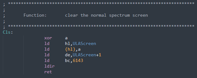
The ClsATTR is exactly the same, but copies an attribute byte to the attribute screen, then uses an LDIR to copy that over the whole screen.
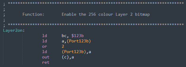
Lastly, we switch on the Layer 2 screen. There’s a few ways of doing this via a Next register or an OUT command. I use the OUT command so I can keep track of the whole Layer2 register value by keeping a mirror of it in RAM. Setting bit 1 on this register switches on the 256×192, 256 colour screen. So far, so good.
Next I set a load of Next registers, so what are these?
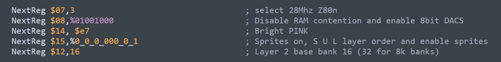
The first one kicks the NEXT into 28Mhz mode, which should be one of the first things you do, so all loading/setup is as quick as possible. Next up is a little known one, which disables ULA memory contention. The original ZX Spectrum slowed down whenever you wrote to address $4000-$7FFF as the screen was also being output to the TV, and the CPU had to share the memory access with that block of memory. The Next doesn’t have this issue, but this keeps it compatible with the 48k Spectrums memory timings so games run at the right speed, and any special effects work the same. Switching this off, means this area of memory will run full speed, giving you a free speed boost.
Next is reg $14 which controls the transparency colour, which we’ll set to “bright pink”. This is an 8 bit comparison so even though the colours are 9 bits (RRRGGGBBB), it’ll only compare to the most significant 8bits of it (RRRGGGBB). This lets us see through from one layer to the other giving us that parallax effect we all know and love.
In order to get the layer view we want, we need to set the layer priority order, and that comes from register $15, where we set order Sprites on top, then Layer 2, then ULA (and tilemap).
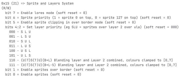
We also enable sprites by setting bit 0, but keep sprites under the border area as this is again a game specific decision.
And finally, we set the Layer 2 base to bank 16, though this is in 16k banks, so that’s bank 32 if you wanted to bank it in via the NEXT banking system. A 256×192 Layer 2 takes 3, 16k banks – a full 48k, which means it’s tricky to have it all banked in at once – but not impossible, we’ll get to that in later articles.
So now we’re all setup, we’ll initialise any global variables we care about – which for the moment, isn’t anything. Now it’s time to hit the main loop
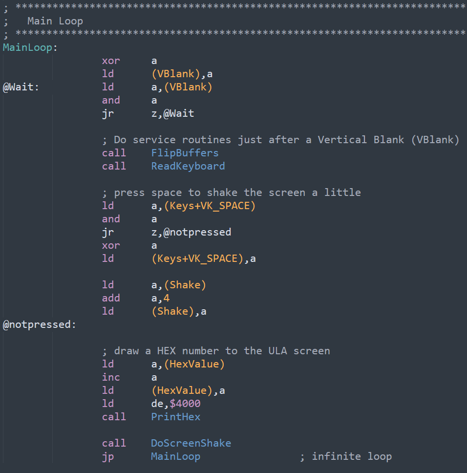
This is really simple for now. First we clear the VBlank flag then wait for the IRQ to set it again, and this means we’ve sync’d to the top of the display. Once we start doing game specific stuff, we’ll likely use a raster interrupt at the bottom of the screen, giving us a chunk more time before the start of the frame, but for now, a VBlank works great.
We then flip buffers – if we need to. In ULA land, that means flipping the main ULA and Shadow screen, or Layer2 buffers. This lets us double buffer the displays so we can draw the screen without any fancy raster chasing – and again, we’ll get to that as we do game specific stuff.
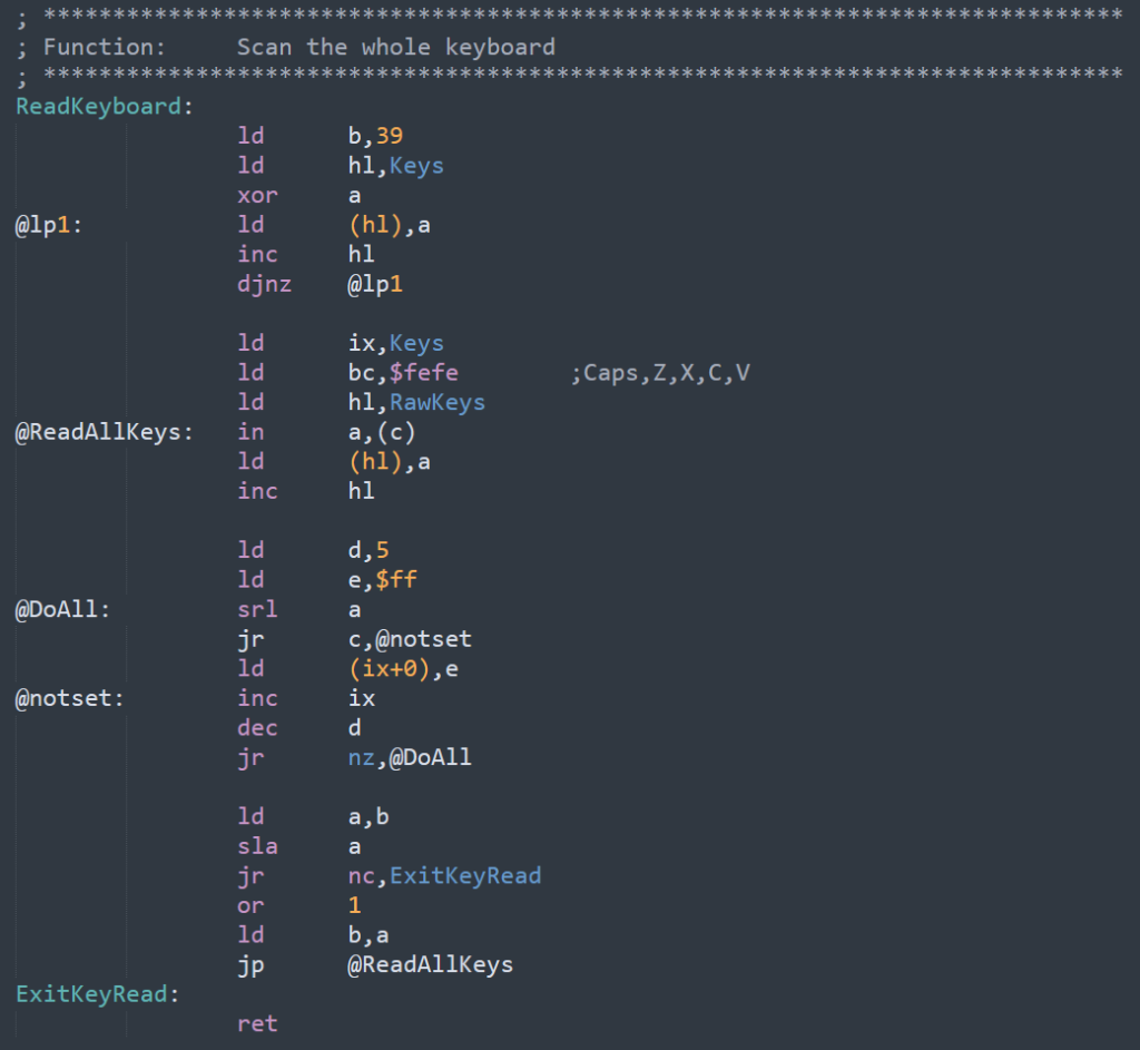
The next part is checking for the space key, I added this in as a simple reminder as to how to check the keyboard, so SPACE will set the ULA screen to shake a little. This is a nice effect you can use to emphasis something – say something heavy hitting the floor, or perhaps a large explosion. To read the keyboard, we IN a,(c) through the different rows, and mark each bit to see if that key is pressed. This is a full keyboard scan so takes a little longer than a game specific reader, which might just check a few specific rows and bits. You can Google the ZX Spectrum keyboard as this is identical, and it’ll show you that each row has a stack of keys in them, and all we do is loop over them all, and AND with each bit, storing a $FF in a 40 byte array when a key is down. There’s a few ways you could speed up even this generic key handler if you really wanted to.
Lastly we draw a little HEX counter to the ULA screen. This is super handy for debug stuff, letting you use the ULA screen to draw some debug info when you need to track stuff in real time. If you clear the ULA screen to transparent, then you can put it over the top of the game, and use it as a brilliant debug screen.
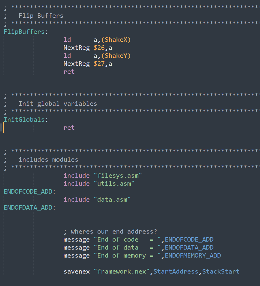
Now to wrap up, you can see our FlipBuffers function just copies in the shake values, but we’d put in the actual double buffer screen flips in here as well, and the InitGlobals is currently empty, as we’ve no game stuff at all yet.
Now I’m going to rewind a bit to have a look at loading.

Here we load 2 files, one into the ULA screen, and the next into Layer2. Now these aren’t “true” files, as they are in what I call my ROM loading system, that is a load of binary data just sitting somewhere in memory to be copied in when we need it. I call it ROM loading as I first used it on the PC Engine where you and a lot of cartridge space, and needed to copy some data into RAM. The filesystem has a few macros to help us, so we’ll take a look at them first.

The macro FILE defines a ROM file, but storing it’s size and base address (bank and offset) into a table for easy access later. SNasm has a handle FileSize() function that can get the size of a file in bytes, that can then be used during assembly, so lets take a look at how the macro uses it.
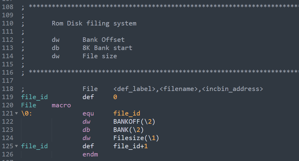
The first parameter is the label we’ll define. This is a handle to the file data, and we pass this in to load the file. This is currently a FILE_ID but could be single byte value if you have less than 256 files, that’s then multiplied by the size of the struct (5) to get the address. We could store the address directly, but abstracting it means it could be stored in another bank, and banked in if need be. You can see each file takes up 5 bytes; 3 for the address, and 2 for the file size. You can also see SNasm has 2 other built in functions BANKOFF() and BANK(). These work out the bank/offset of any physical address – like where the file was assembled to.
So how do we load it? Well the LOAD macro is just as simple…
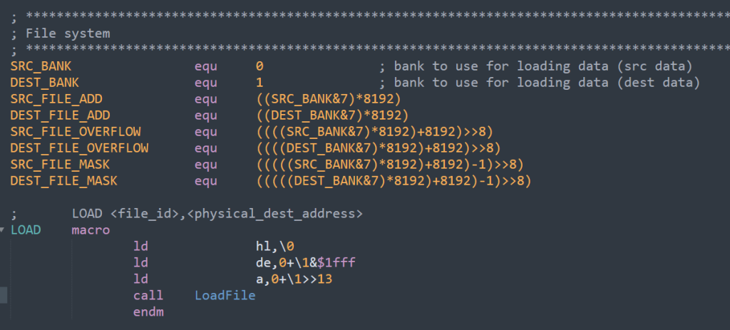
Here you see HL is set to the FILE_ID, and then we specify the physical address of where we want to load – that is the full address from 0 to 2Mb, not just somewhere in the mapped 64k. This means we can load level data to anywhere in memory without having to faff around with banking stuff in/out first, and that makes like much simpler.
Above this you’ll see a load of defines. These specify which 2 banks you want to use for loading, and these can be any of the 8 banks – though watch out for the bank with the IRQs in it. I’ve opted to bank over the ROM area, as that’s my general purpose data area, so I use banks 0 and 1. 0 is used to bank in the source data, and 1 is the target memory.
Now, you could use this data directly without copying it, but much of the time you want to modify level data on the fly, as you play the level – or even remap/redefine graphics positions, so copying the data in abstracts things nicely, and makes it easy to reset a level. There’s nothing of course stopping you from doing both as needed.
So what does the actual LoadFile function look like? Well, lets look at this in two parts.
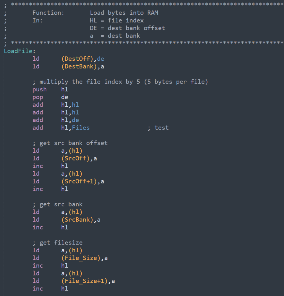
First the setup. This simply takes the file handle, multiples by 5, and copies the base address and size out. If the file data was in an external bank, we could bank that in first, leaving more of the 64k free for actual game data.
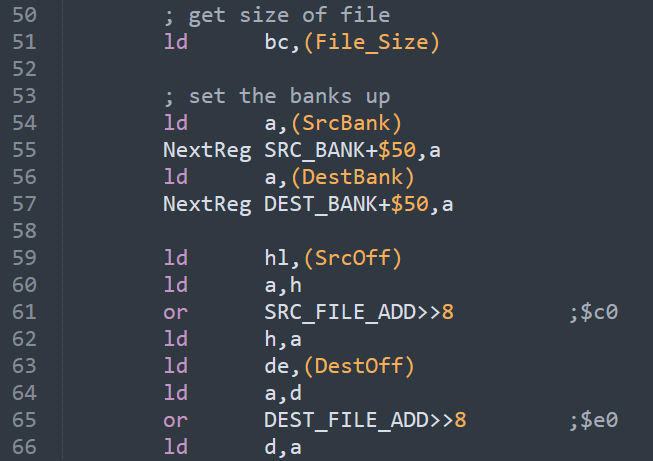
Next we setup the MMU and bank in the first bank of the source, and destination, while OR-ing in the banking base address. With that done, we’re ready to start copying file data…
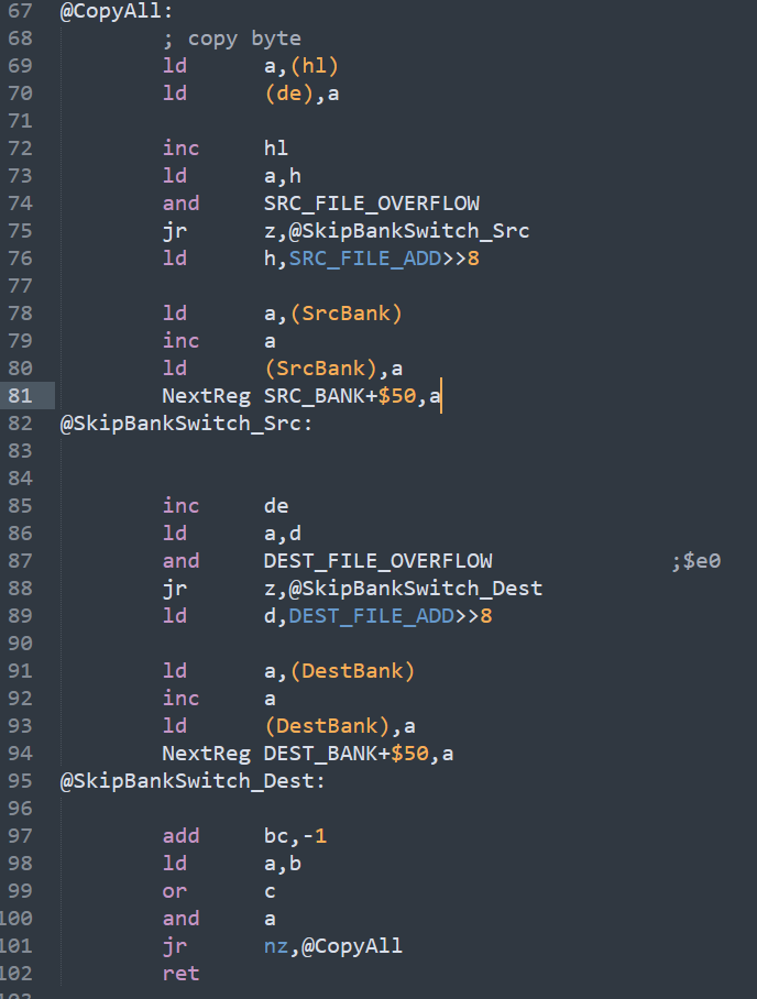
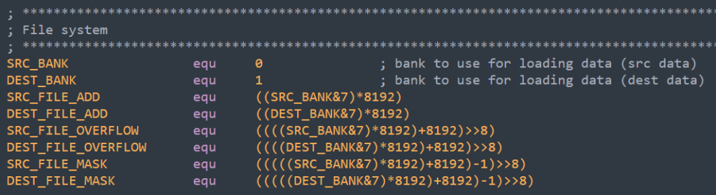
So the loading loop is pretty simple, copy the byte, and increment the address pointers. The “trick” comes when we detect it’s gone outside the source/dest bank and we then need to increment the bank number and reset the address to the start of the bank. I do this by checking to see if the bit that defines the base address disappears. So what do I mean by that? Well, if the bank base is $2000 then the bank will run from $2000 to $3FFF, that means when we hit $4000 we need to reset back to $2000 and increase the bank number. Lets look at that in binary…
$20 = %00100000
$3F = %00111111
$40 = %01000000
So as you can see when bit 5 stops being a 1 (and bit 6 turns into a 1), then we’ve crossed a bank boundary, and need to reset. Each bank has it’s own “bit” to check for, and that’s what all those defines do, works out the banks/bits/masks
So lets look at the source increment – the destination is the identical.
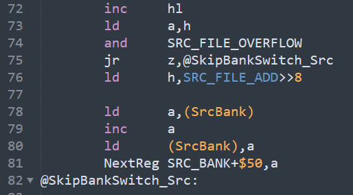
We increment the address, then we copy the high byte and then AND the bank base address bit to see if we’ve swapped bank, if not we carry on, if we have, then we copy in the base address high byte and reset it. After that we get the bank, increment it, and set the Bank to the new one.
We then just decrement the file size and carry on until we’re done – and that’s all there is to it.
So, there we go, the first version of the framework. I intend to put more into this to help setup sprites, and perhaps put my sprite cache in as well. This will help extend the sprite “shapes” beyond the 128 that you normally have.