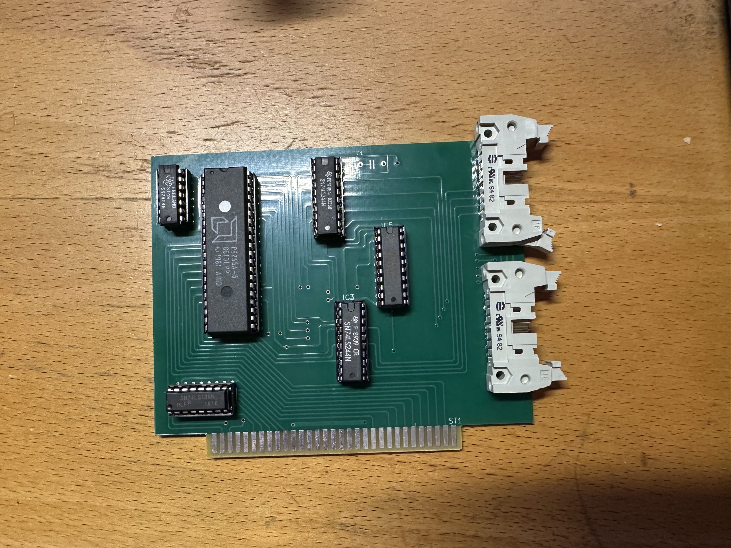
Well, this has been quite the journey. Last time I said I’d found an EAGLE board file, but it appear to be shrinking it, making the board the wrong size. Well, I managed to import it into KiCad and then export to a new bunch of GERBER files, and after watching a Mark Fixes Stuff Video about submitting to PCBWay, and fixing the way over the top cost of adding an edge connector – I thought what the hell….
I uploaded the new GERBER files and tried to purchase 10 boards. I thought it was going fine, only to have PCBWay stuff come back to me with several issues. The first being the original EAGLE file didn’t have a continuous board outline – for cutting. Having never used KiCad in anger, I had no idea what I was dong. After much random clicking, I finally found the outline hidden in a “parts” thing; yeah… I’ve no idea either. I managed to extend the line and create a board shape, re-exported and then tried again. This time, I had too many layers for the 2 layer board I was trying to make. The file has loads of layers, the board stuff and comments etc. I removed what I thought I needed and tried again.
This time, the edge connector wasn’t right, as it went outside the physical board, and the PCBWay guys offered to “ignore” this part. I’ve no idea why it was there in the first place, perhaps it’s an EAGLE cad thing.
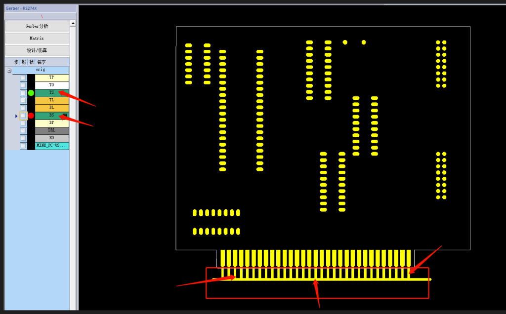
After this is the most confusing one… and one I’m not 100% sure I’ve resolved.
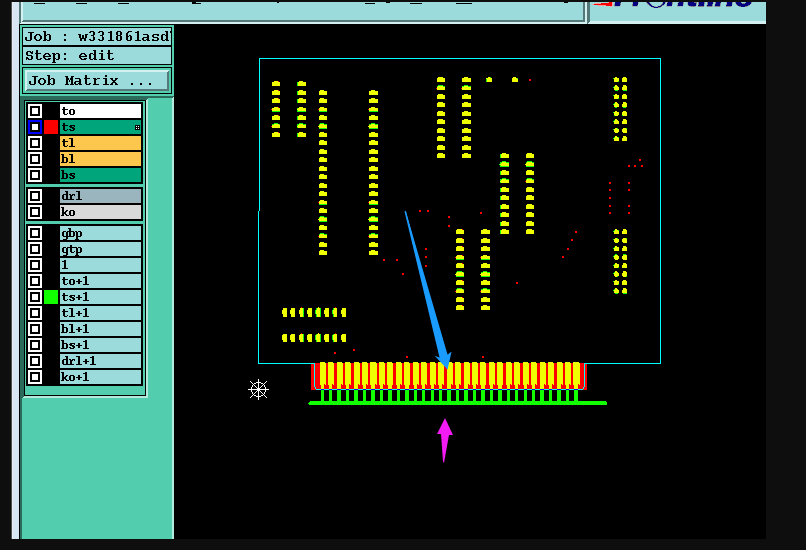
What they’ve told me, is this…
“…there is soldermask bridge between the pads for the edge connector,so there is no soldermask opening on the edge connector area.
A:we suggest to make according to your gerber file,and you can accept the soldermask ink will fall off and poor solder.
B:we suggest to make complete soldermask opening for the position of edge connector and there is no soldermask bridge between the pads.Like the pic4″
I don’t understand what they mean here – I may have to ask someone with a bit more of an understanding of this stuff to tell me how to fix it before putting it up on the community hub….
Once I fix that, I can make a final test run and make another load of updated boards, making sure the export and make process is seamless, and then I can release the files.
So…. once I got these boards back, I set about comparing sizes etc as I still wasn’t exactly sure it was the right size etc.
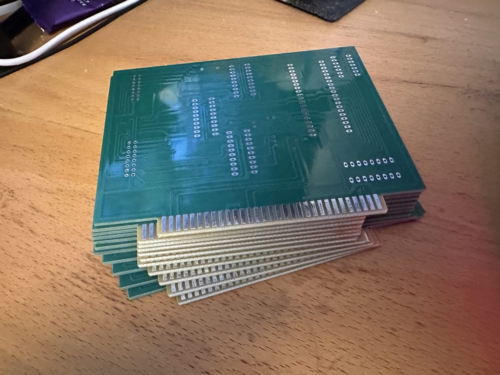
But as it turned out, it was BANG on!!
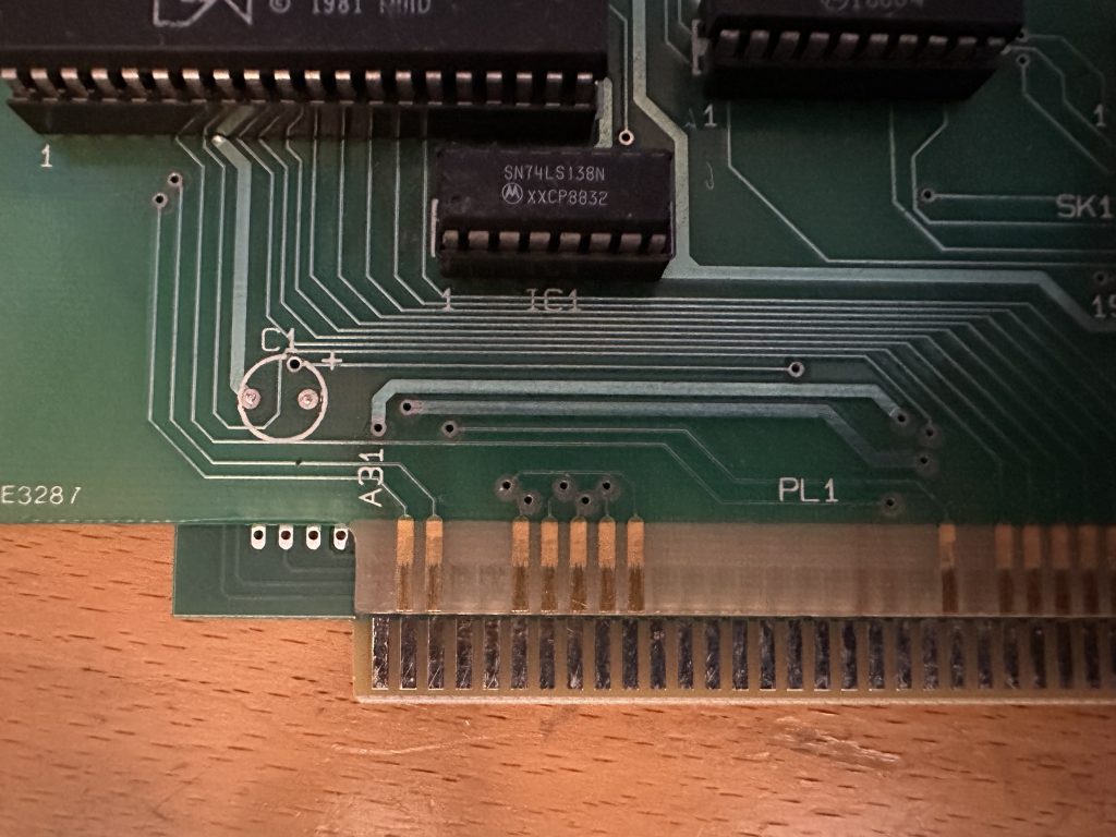
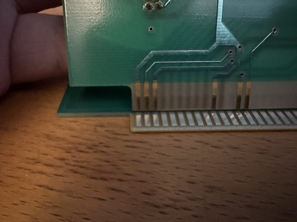
This was AMAZING!! I then set about making sure the edge connector connected to the same pins as the original board, which should then mean even if the board doesn’t work – it shouldn’t blow the machine up! Once I verified that the edge connector was wired correctly, I needed to populate it.
So I set about ordering parts to try and solder one up. Those big chips – the P8255A-5 aren’t made anymore, so eBay was the first port of call, and I managed to get 5 of them pretty cheaply. I’m avoiding anything from China, as the amount of dud/fraud/dead chips from there, is just making it not worth the risk. There are lots of places in China where you CAN get good, cheap components, but I’ve had so many fake chips, that I’ll avoid buying there if I can.
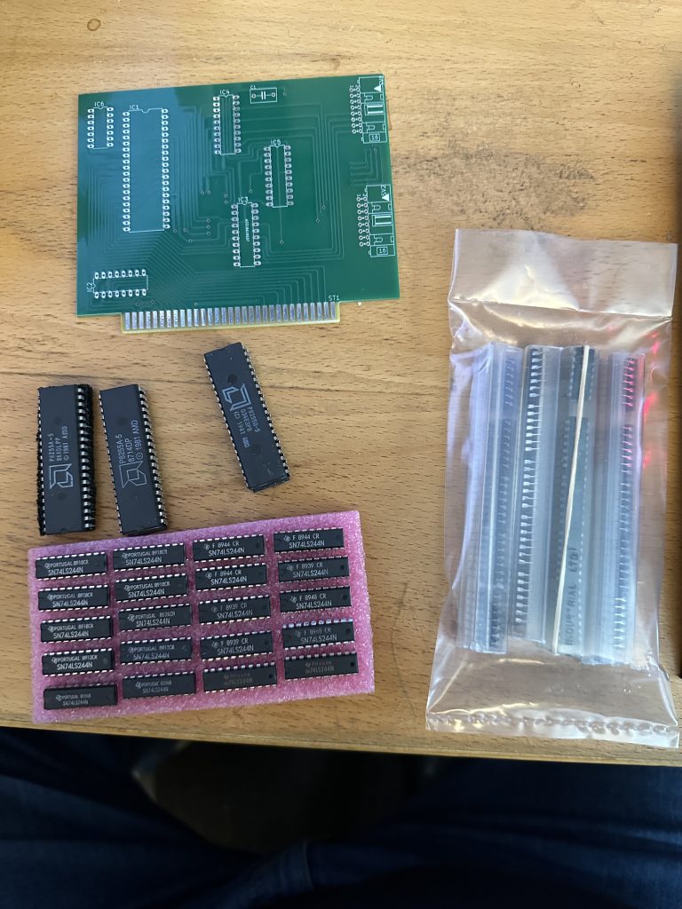
I was also going to socket everything – as you should if it’s your own board, so I had to buy a load of sockets too. These were really cheap ranging from £0.17 to £0.65 per socket. But it does all add up when you buy enough for 10 boards.
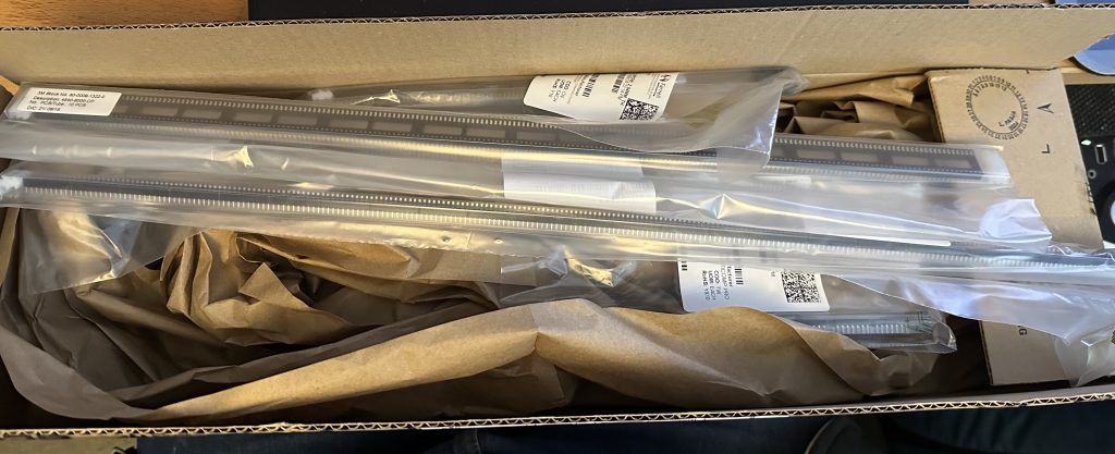
Once everything arrived, it was finally time to solder one up. I spent a day clearing my electronics desk – as it was COVERED in rubbish, and then set to work on it.
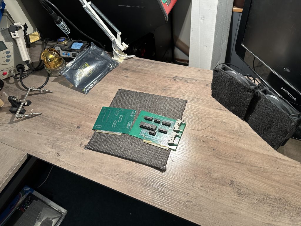
These are really easy – an quick, boards to solder up. No resistors or capacitors (though there is space for one, but it never seemed to get used).
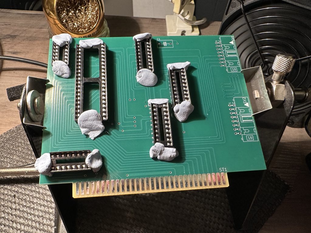
You’ll notice I opt to follow the Mark Fixes Stuff soldering method of using Smurf Poop™ to keep things affixed. This works great – as long as you make sure everything is flush before starting! I had one socket that wasn’t, and didn’t notice, so had to de-solder it and start again…
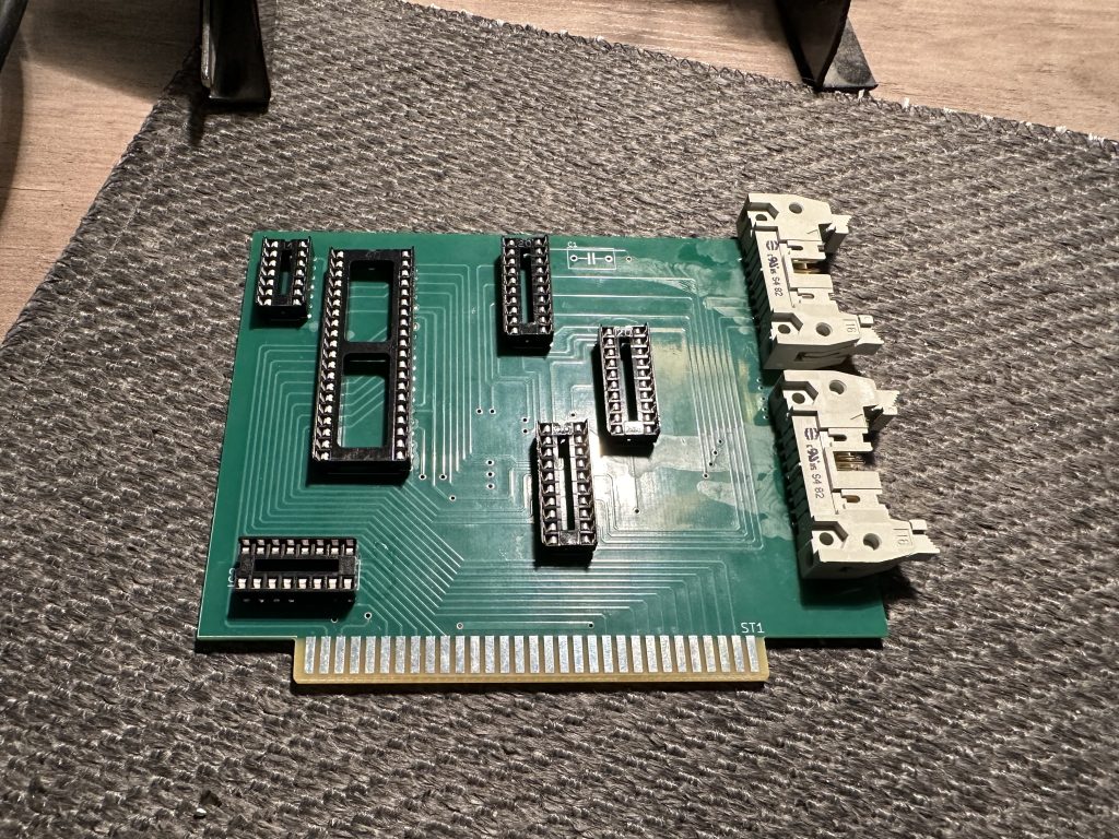
Now was the moment of truth. Stick the chips in, an then plug it in and see if it works! I’d setup the one I’d gotten from (wonderful) Kev Brady, so now it was just a case of swapping the card and seeing what happens. I was extremely nervous to say the least…. My decidedly amateur level of knowledge at electronics means this is the first card I’ve ever gotten made – even if I didn’t design it, I understood the process and had laid a board out before and created a home board before, but just never followed through and got a “proper” board made.
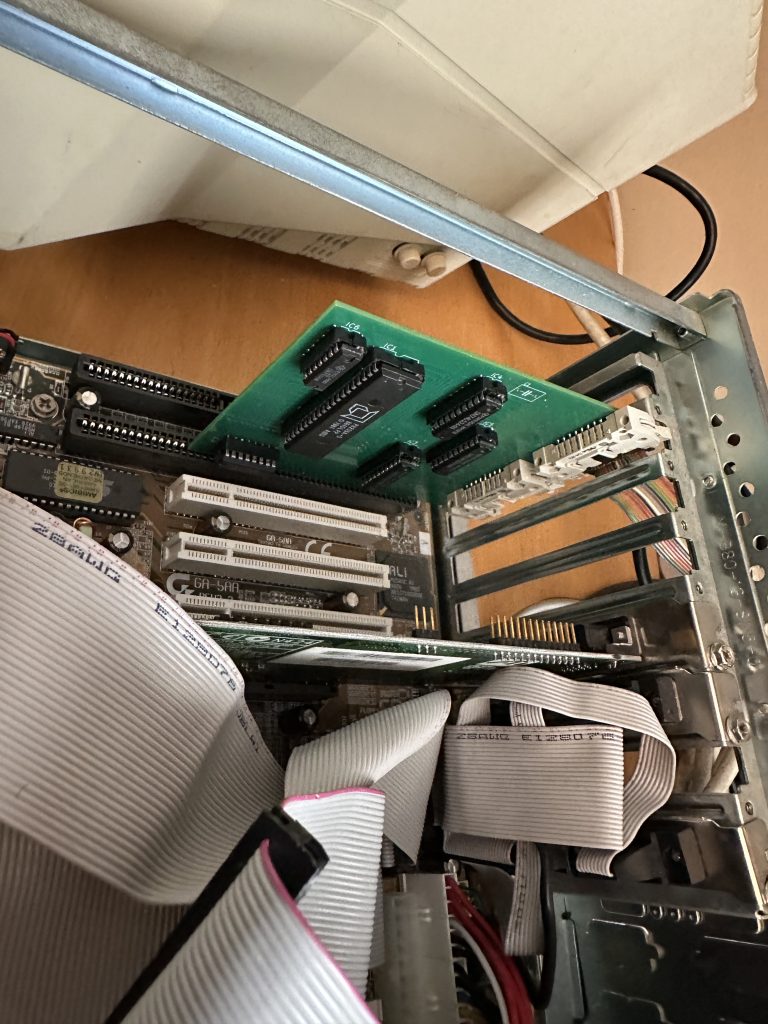
The cable connectors are a little too short it turns out, the original having slightly longer arms to clip in. No matter, it still plugs in and still fits fine
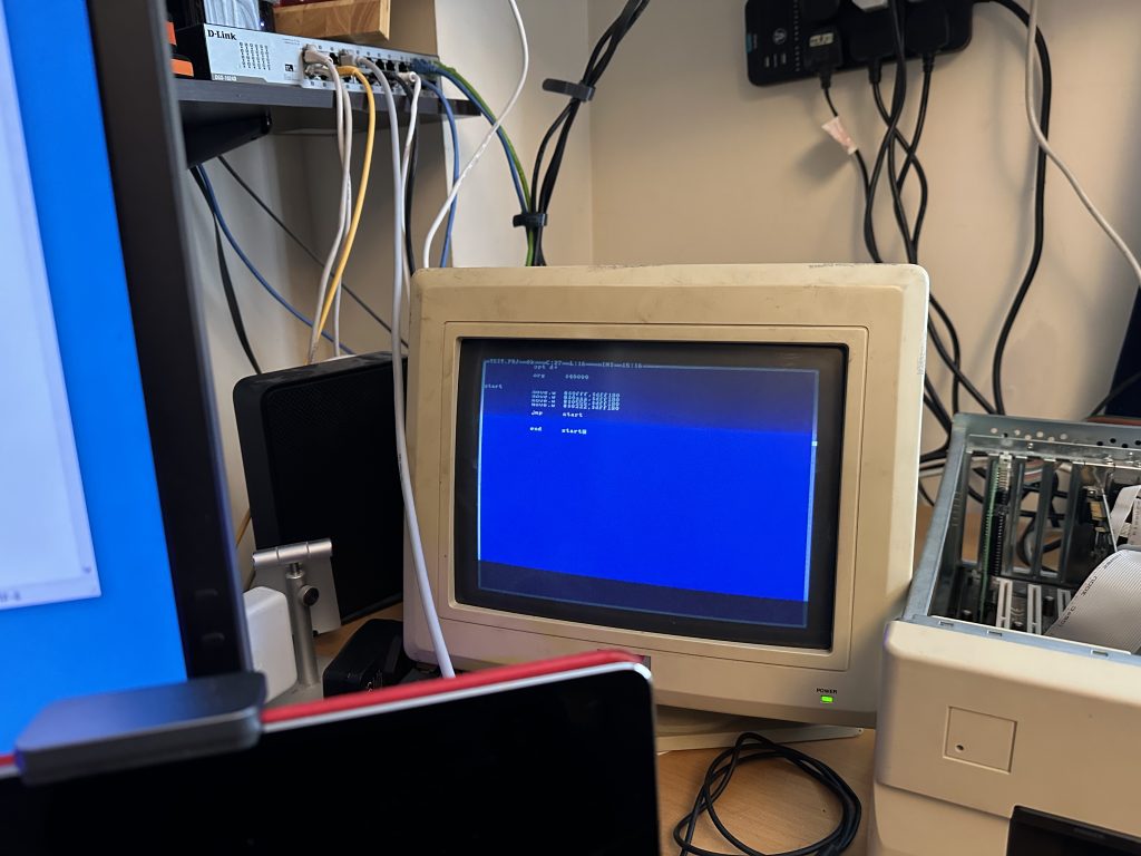
. This was connected to my A1200, so I loaded PDS2 wrote a little colour changing loop, and compiled it…. and….
BANG!!! IT WORKS!!!!
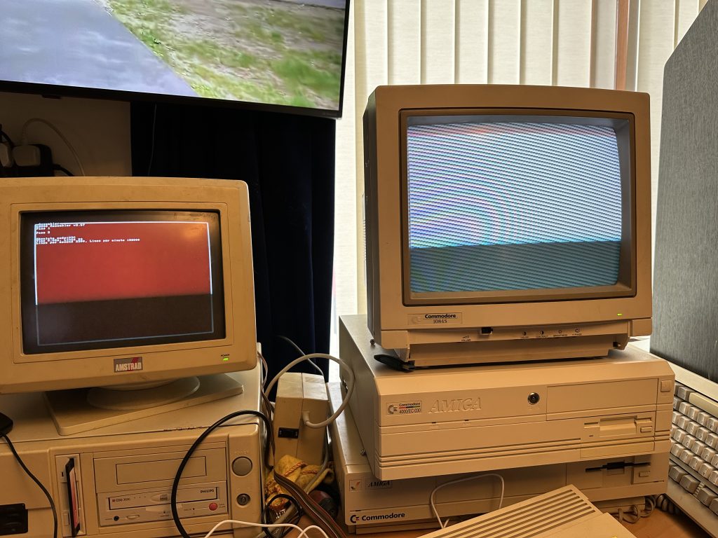
It just works!! I was amazed at this. First time, Bang!
The plan is to do some Amiga dev at some point, ideally with the A4000, but for some reason, the A4000 won’t power on with the Parallel cable plugged in. No idea why. It’s exactly the same as the A1200, and it boots perfectly.
I do have a ZZ9000 card in there, so it’s “possible” that might be interfering, though I’m not sure why as there are no power lines connected in the parallel port. Oh well. A1200 works fine.
And the most important part of the system, getting into the debugger!
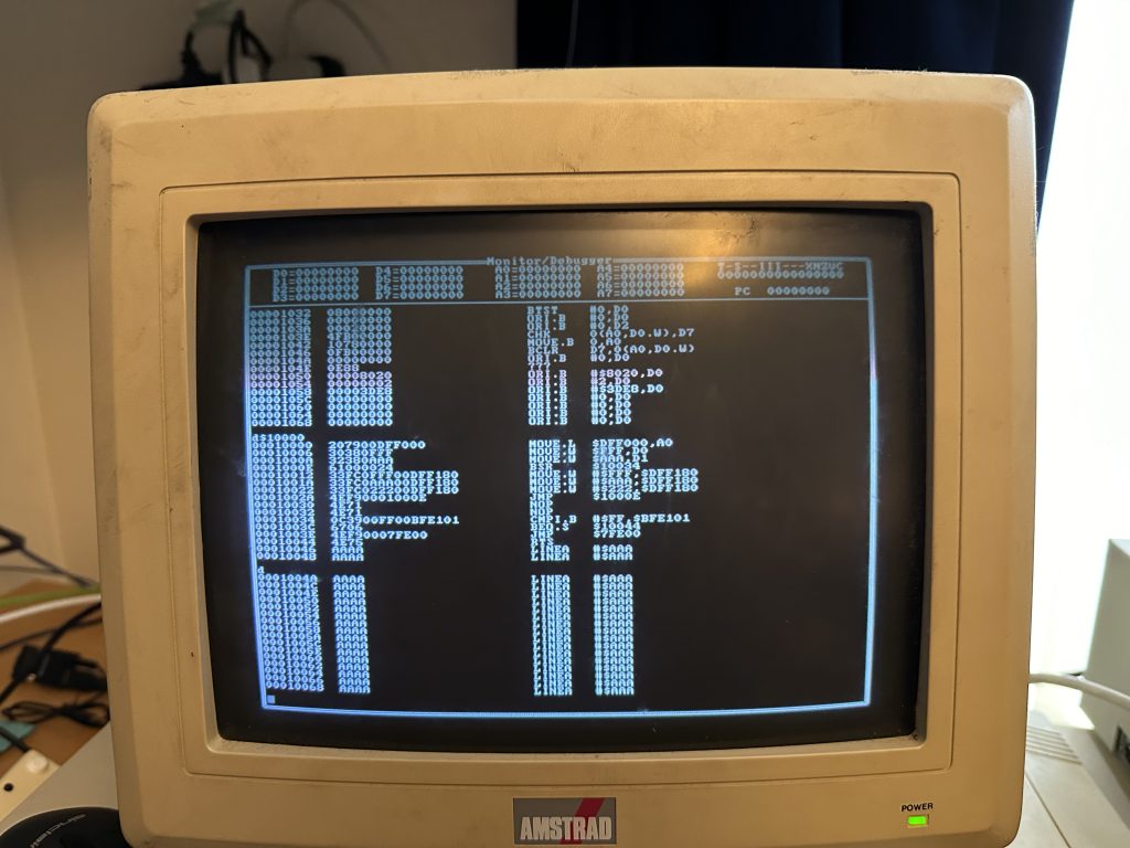
This seems to work perfectly as well, and there’s nothing quite like debugging on REAL hardware.
Once it was all working, I one some to dev friends, and started making a few spares. I promised a spare to Kev, and Jason at the RMC DevDen, and a couple of others. So from having none and having the like “gold dust” card, to having 6 and being easy to make spare is just amazing.
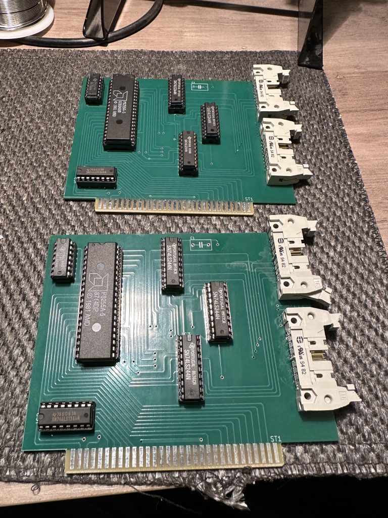
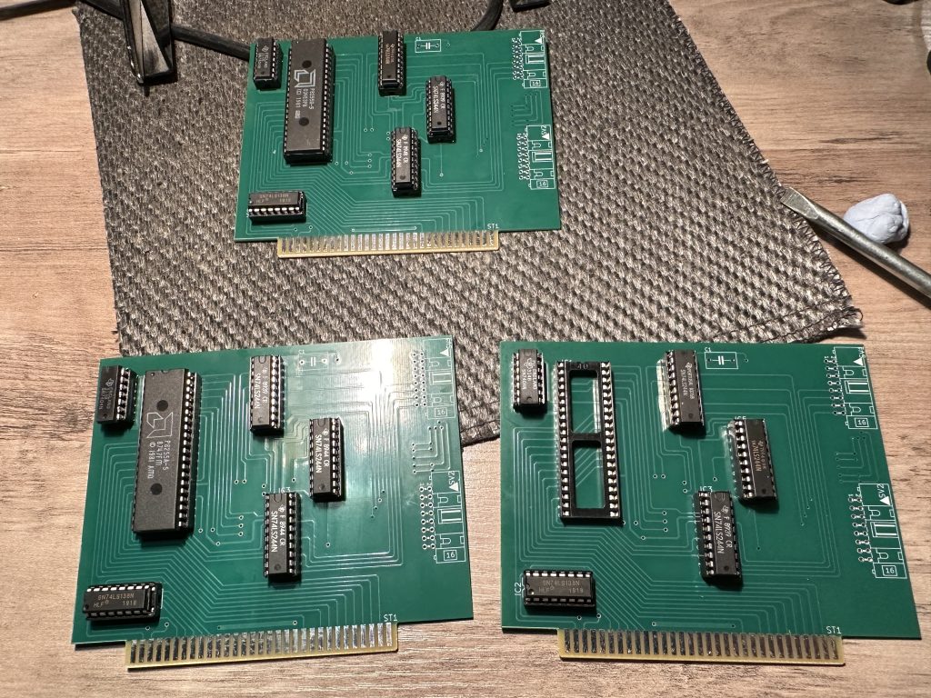
Here’s the finish version, all tested and ready to be sent out to people.
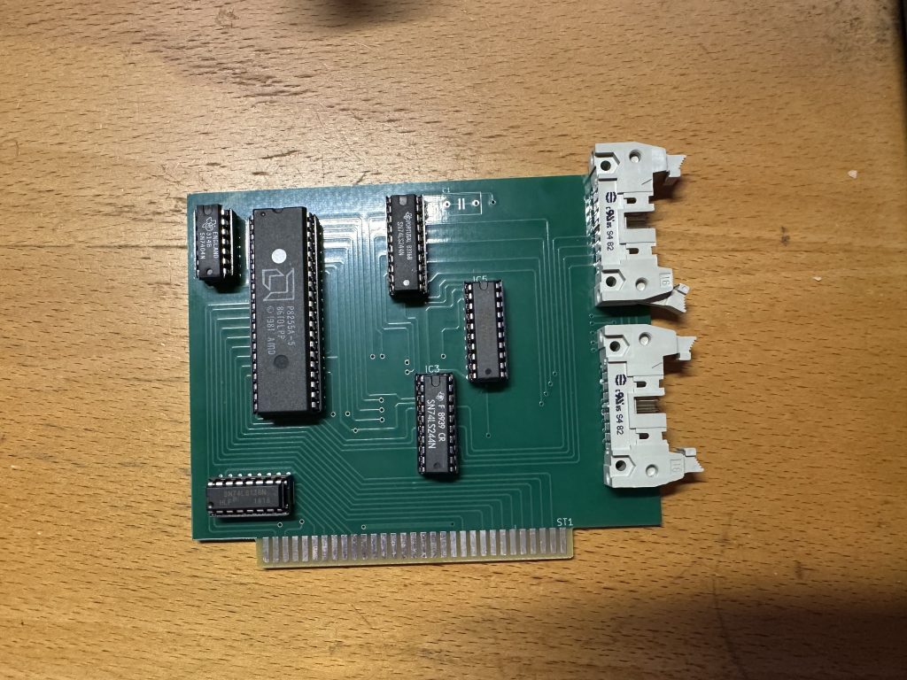
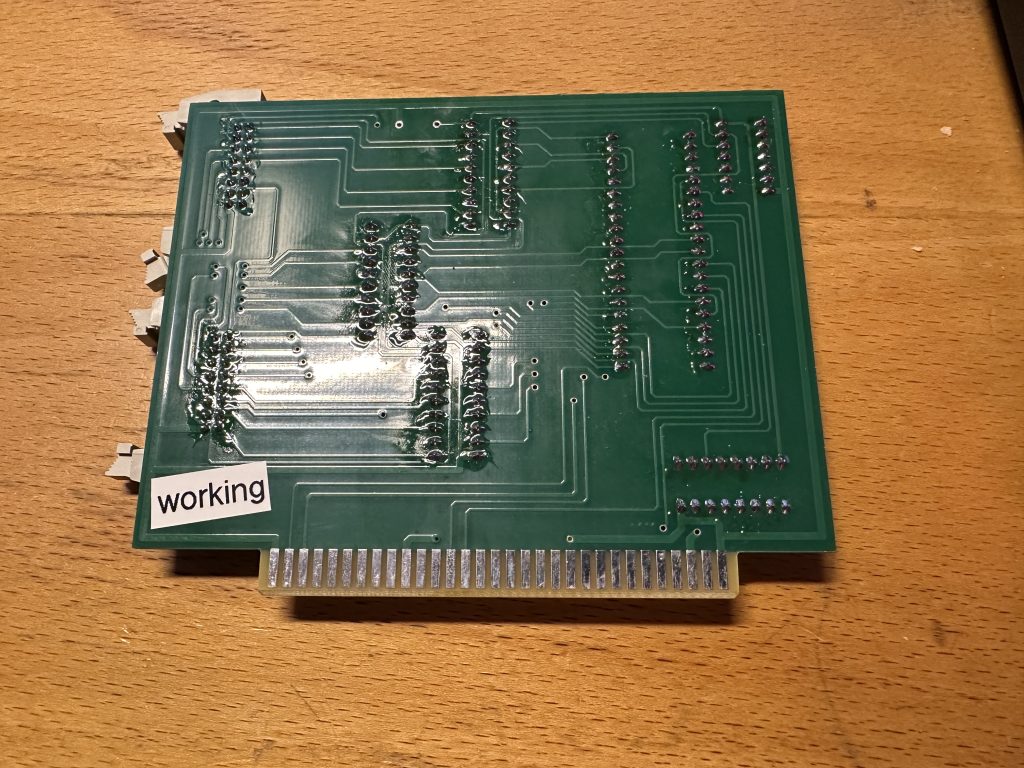
I will likely sell a few on eBay – in an attempt to recoup some of the costs (it was a few hundred quid to get this point, and I’ve a little more to go on it). But it WILL go up onto PCBWay’s community project hub, for anyone to get and make.
Before that happens, I need someone to help fix this last edge connector issue, then I need to make a final batch of boards to make sure it all works. The new board is a little nicer, with everything labelled this time, as the original wasn’t.
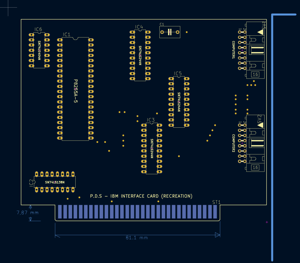
In general, you’ll need to order a min of 5 boards I suspect, and then with the components, you’re probably looking at around £80-£100 to make one, though you’ll have a few spare boards left.
This card will work on PDS and PDS2, and it appears to work on all systems; Amiga, ST, C64, Spectrum, Amstrad, BBC and MSX (I’ve also heard of Sega Master System and PC Engine, but the target hardware is unknown…). It’s an ISA card and wants to run under DOS, though I have gotten it to work under Windows 98, but I had to make sure 640K is listed as installed (some cards reduce this), and use for the PDS exe to actually work, as it didn’t like what Win98 returns.
Once you’ve done that though… it does work just fine. The various exe’s are out in the wild, and I’ve managed to get the Z80 and 6502 exe’s fairly easily.
At some point, I also want to recreate the ZX Spectrum/Amstrad and ST hardware so we can use those systems as well. The Amstrad board looks simple enough to recreate, it’ll just take time. I’ve never used an Amstrad, but I’ve a couple in the loft… so one day.
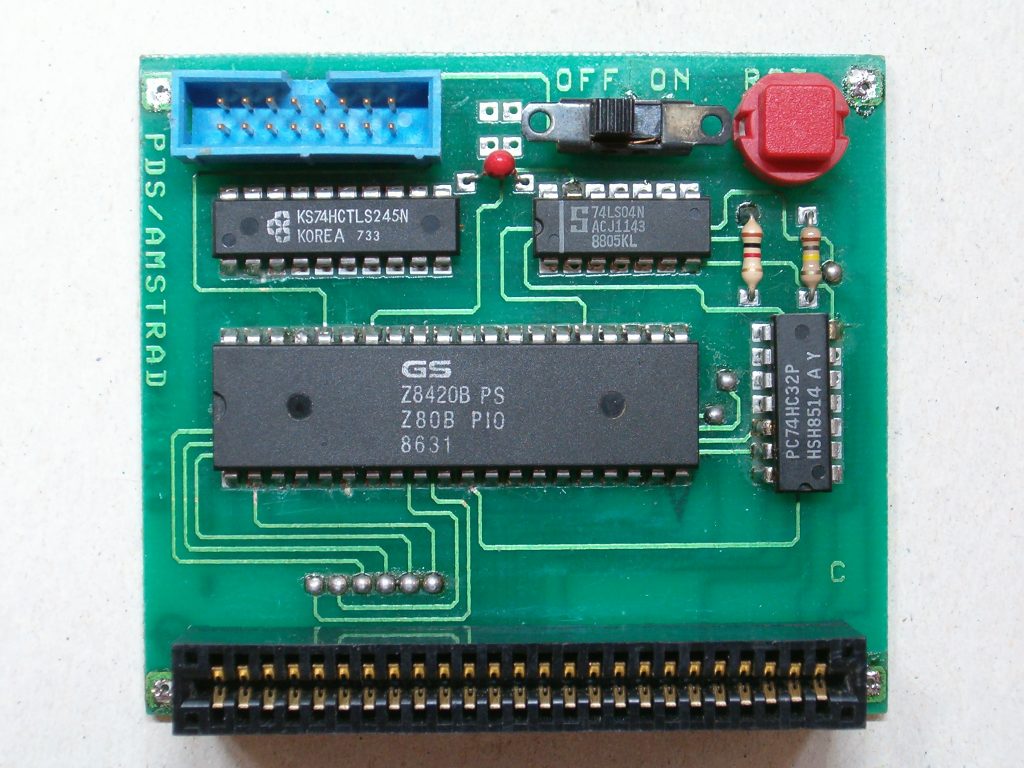
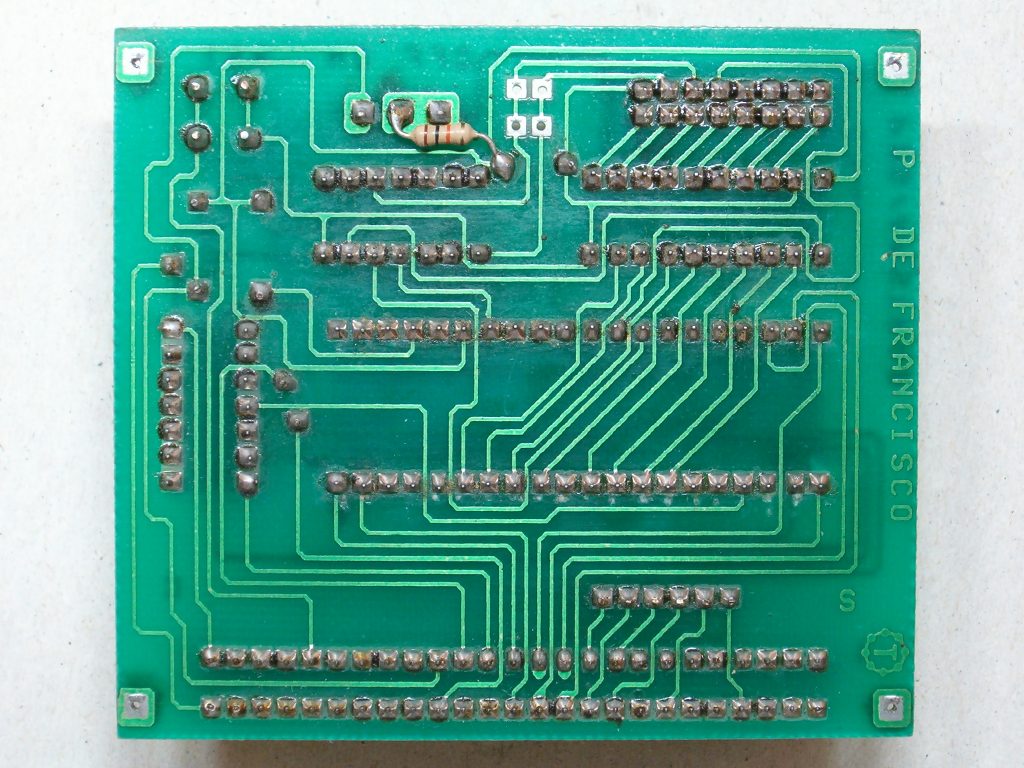
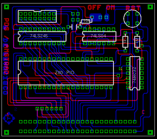

The Atari ST one (below) I’m not so sure about…. it actually looks like a controller, not a target. Why would you need 2 input sockets, unless your controlling 2 computers? it’s a bit weird.
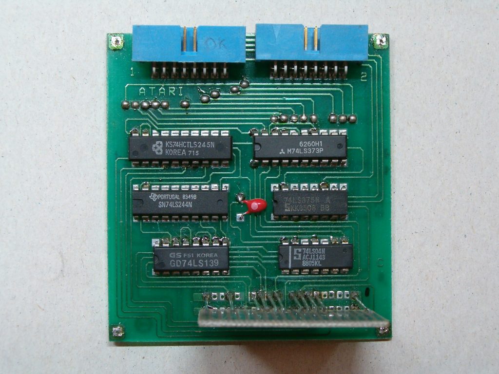
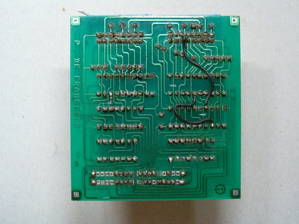
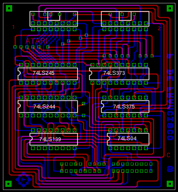
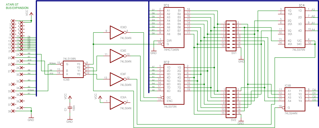
I don’t have the board files for this, but again I can probably recreate it easily enough. I don’t have the target software for this one either, so that’s another complication.
The MSX one is a cart looks very close to the Amstrad one, but this is the only image I have, so making this one would be more complicated, and again… I don’t have the software end for this one either.
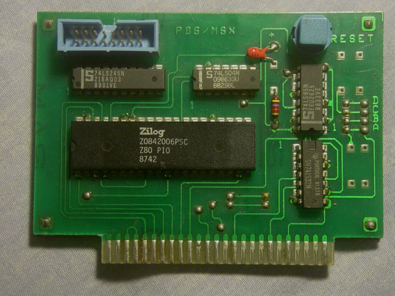
The Spectrum one looks just the same, and is probably just connecting to a different edge connector.
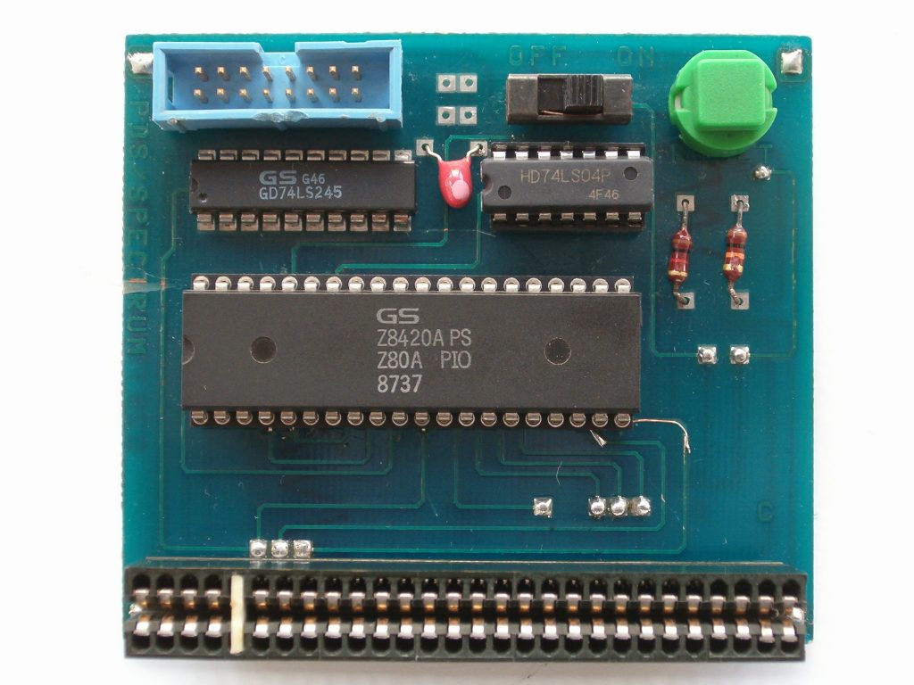
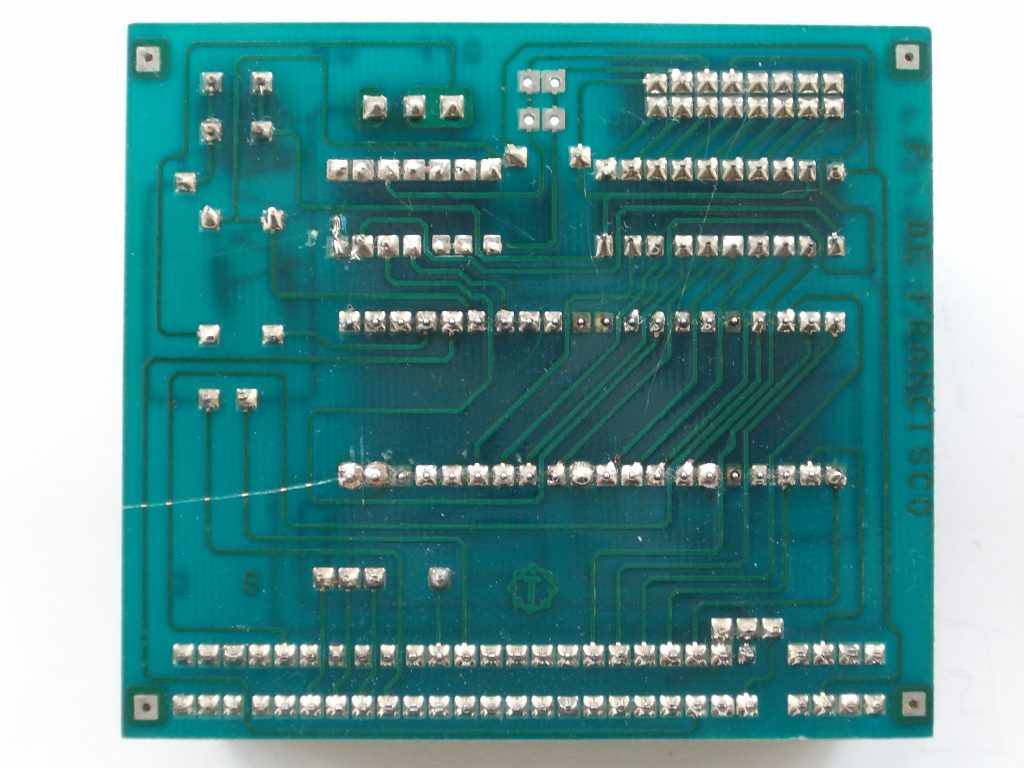
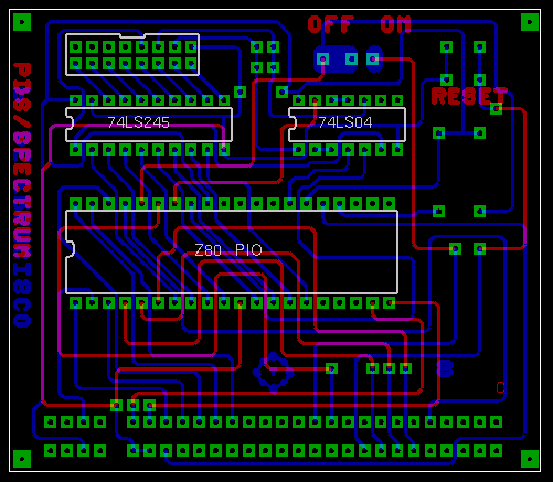
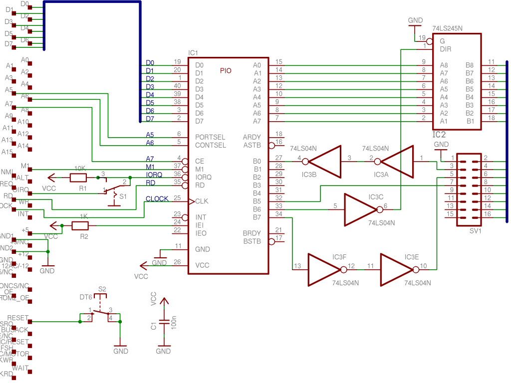
Being able to code a speccy like this could also be a lot of fun. I suspect that the ZX Spectrum Next could also be controlled like this, but I’m not sure…. I’d still prefer using the Wifi as the debugger – which I do have a framework for, but need to finish.
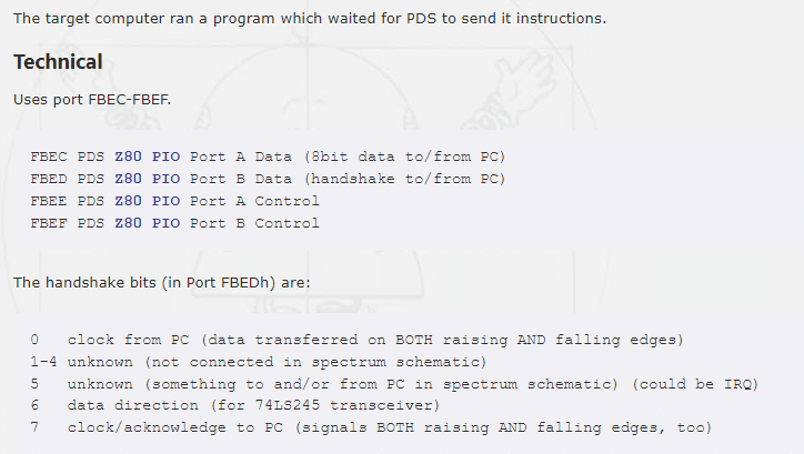
This is the Z80 mapping, which could help remake the MSX one….
I’ve not even SEEN the BBC end, so I’ve no idea how that works – though I do have the download target code for that.
All this info – board pictures and layouts etc. were taken from several different sites. They do have a habit of disappearing, so I’ve copied them all to keep them safe. Here are most the different sites, though I did pick up some bits from a few random sites.
CPC Wiki
Article by retro-hardware
Andy Glaister – Work History
Article on P.D.S (Spanish)
World of SAM PDS article – and an edge connector converter?
Euro convertor pinouts – for a converter to SAM
I did make a PDS<->Amiga cable as well, this was a horrible thing to solder up, but it did work fine. The pinouts are shown below – looking into the end of the cables, not the ports.

Jason at the RMC DevDen was kind enough to workout the C64 pinouts for me as well, so I’ll need to make up one of these. I’ve got 2 old C64 PDS projects (Ballisitx and Blood Money), so it’d be fun to see them working again, though I put PDS support into SNASM a while back….

Once again, I can’t thank Kev Brady enough for lending me his Amiga PDS kit, without his generosity, I’d never have been able to do this. He even had the Amiga boot disk, and I’ve been able to back this up using RobSmithDev‘s Amiga floppy system – DrawBridge. So now the Amiga PDS is totally back up, and reproducible – which is awesome.
The end goal, is to get the rest of them working as well. The old PDS was great fun, and I loved using it, so it’d be great to save it from total oblivion. If you have any of the missing systems, please get in touch, and lets see if we can recreate it, and save it.
This has been an adventure into the unknown for me, and it’s been great fun, but it’s just the start….
